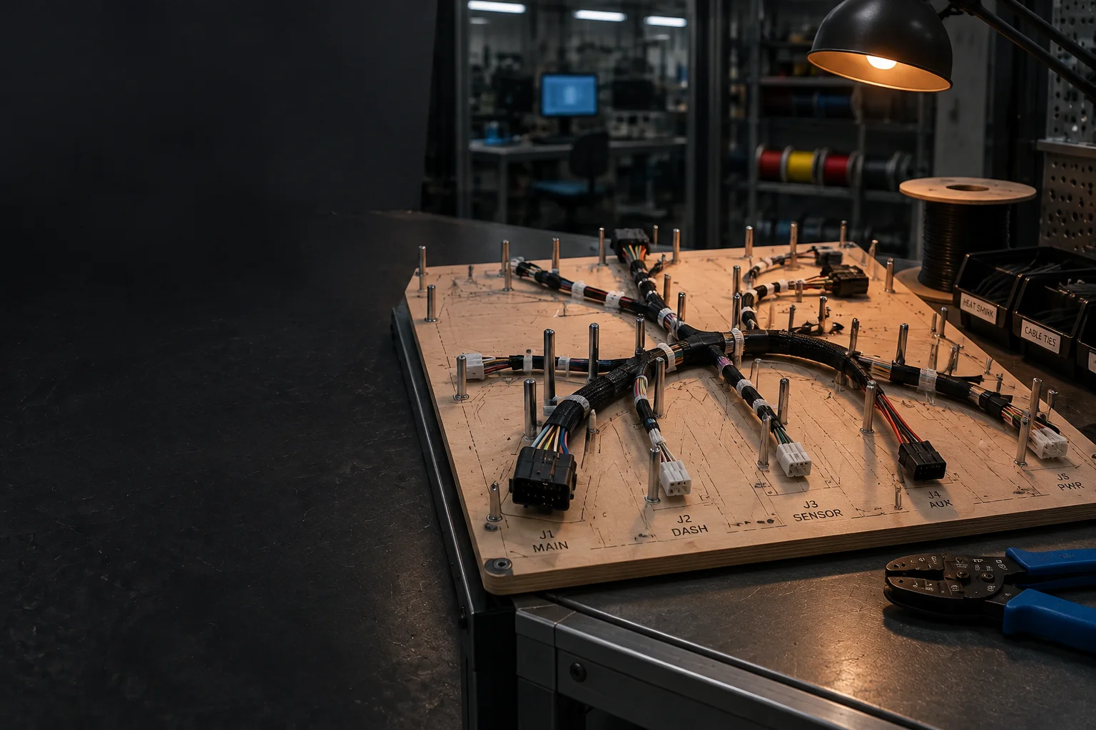
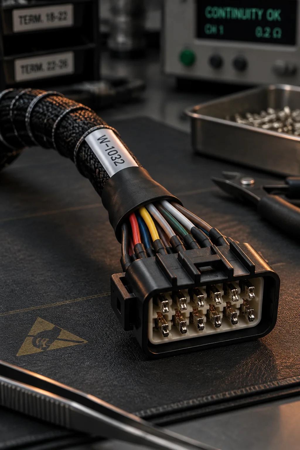
Wire harness pinned out on a routing board with crimped terminals, sleeving and labelled breakouts

Capability / Cable, harness and electro-mechanical

Cable, Wire Harness and Electro-Mechanical Sub-Assembly

A harness is the part of a build that is most often tested by hand and least often documented, which is why cable faults show up as intermittent field returns rather than as line failures. We build to a released wire list, prove every crimp with a pull test, and verify continuity against the drawing before the assembly leaves the bench.

Box build

AWG 30-8 discrete wire range
IPC/WHMA-A-620F workmanship class 1 to 3
100% continuity and pull test on every harness

How a harness is built

Pinned to a routing board, tested before it is dressed

Routing boards and the cut list

Each harness gets a routing board with the breakouts, bend radii and tie positions pinned out at full scale, built from the released drawing rather than from a sample. Wire is cut and stripped to the lengths on the wire list with a tolerance of plus or minus 2 mm on a breakout and plus or minus 5 mm on a run, and the strip length is held between 3.0 and 6.0 mm so the insulation sits inside the crimp barrel without entering the contact area. Every wire end carries its circuit identity until the label is fitted.

Crimp criteria that are measured, not judged

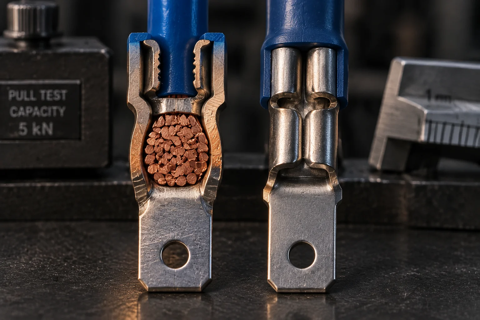
A crimp is accepted on three observations: the conductor is visible in the wire barrel with no severed strands, the insulation support grips the insulation without cutting it, and the bell-mouth is present at the brush or ribbon end. Where the class requires it we measure crimp height with a micrometer against the contact manufacturer's specification and pull three samples to the IPC/WHMA-A-620F tensile minimum for that gauge. The applicator is set once per job and the setting is recorded, so a re-run of the same part number crimps to the same height.

Electro-mechanical integration

Harnesses that become part of a box build are dressed into the enclosure on the same routing discipline, with sleeving and grommets at every panel pass-through and a service loop left where a connector has to move. Fasteners are torqued into a logged band of 0.4 to 4.0 newton-metres, strain relief is verified by hand before the cover goes on, and the finished unit runs a system-level functional test so a mis-pinned connector is caught in the cell rather than at the customer site.

Vertical view of a harness routing board with wires pinned at the breakouts and crimp terminals staged along the branch

Capability table

Gauges, crimp types and the pull test that proves each one

Twelve rows covering the wire range we build, the termination methods available, the tensile minimum applied to each gauge band and the workmanship class that governs the call.

Cable and harness capability - pull-test minima from the IPC/WHMA-A-620F tensile tables
Item Capability Acceptance criteria Standard and class
Discrete wire range AWG 30 to AWG 8 in PVC, PTFE and silicone insulation Strip length 3.0-6.0 mm, no nicked or severed strands, no insulation pull-back into the barrel IPC/WHMA-A-620F Class 2
Fine gauge and micro-coax AWG 32-28 wire and 0.8-2.0 mm coaxial cable Clean strip, shield braid dressed without strand loss, dielectric undamaged IPC/WHMA-A-620F Class 3
Open-barrel hand crimp AWG 26-14 for low volume, repair and field kits Conductor visible in the barrel, insulation support closed, bell-mouth present, tool calibration logged IPC/WHMA-A-620F Class 2
Bench-press applicator crimp AWG 28-10 at production volume, with a cut-and-strip machine feeding the press Crimp height measured per setup, then verified every shift against the contact specification IPC/WHMA-A-620F Class 2 and Class 3
Four-indent crimp AWG 26-12 on military and aerospace contacts Indent depth and position per the contact manufacturer, no deformation of the contact body IPC/WHMA-A-620F Class 3
Pull test, AWG 28-26 Minimum hold before separation 15-22 N applied axially at 25 mm per minute IPC/WHMA-A-620F tensile table
Pull test, AWG 24-22 Minimum hold before separation 22-40 N applied axially at 25 mm per minute IPC/WHMA-A-620F tensile table
Pull test, AWG 20-18 Minimum hold before separation 55-90 N applied axially at 25 mm per minute IPC/WHMA-A-620F tensile table
Pull test, AWG 16-14 Minimum hold before separation 130-220 N applied axially at 25 mm per minute IPC/WHMA-A-620F tensile table
Pull test, AWG 12-10 Minimum hold before separation 260-400 N applied axially at 25 mm per minute IPC/WHMA-A-620F tensile table
Solder termination AWG 30-16 on cup, hook and turret terminals, plus splice joints 75% minimum circumferential wicking on the barrel, no insulation damage, no cold joint J-STD-001 Class 2 and Class 3
IDC and ribbon cable 0.635 mm pitch ribbon and 1.27 mm insulation displacement connectors Full insertion with the strain-relief cover latched, no displaced conductor and no partially pierced strand IPC/WHMA-A-620F Class 2

Harness services

Harness services: the scopes we quote from a drawing

Six scopes cover the work we are asked for. Each one is quoted with its own verification step, so a harness never ships on a visual check alone.

SVC-01 / Design support

Routing-board and wire-list review

The drawing is checked for missing branch lengths, connector position numbering, circuit identity on every wire end and a bend radius the cable can actually take. Where the drawing is silent, we say which dimensions are missing instead of filling them in from a similar job.

Input
Released drawing, wire list, connector datasheets
Output
Routing board plus a build traveller per harness

SVC-02 / Preparation

Wire cutting, stripping and tinning

Automated cut-and-strip for AWG 30 to AWG 12 with the strip length held between 3.0 and 6.0 mm, and hand stripping with a calibrated tool for the heavier gauges. Tinning is applied only where the termination calls for it, because a tinned conductor under a crimp barrel changes the cold-flow behaviour of the joint.

Gauge range
AWG 30 to AWG 8
Length tolerance
+/- 2 mm on a breakout, +/- 5 mm on a run

SVC-03 / Termination

Crimp and applicator termination

Open-barrel, closed-barrel and four-indent crimps on hand tools and bench presses, with crimp height measured against the contact manufacturer's specification. Three samples are pulled at every setup and then every 500 crimps, and the pull values are recorded against the harness serial.

Verification
Crimp height plus tensile test to IPC/WHMA-A-620F
Class available
Class 1, 2 and 3

SVC-04 / Ribbon and coax

IDC, ribbon cable and micro-coax

Mass-terminated ribbon on 0.635 mm and 1.27 mm pitch with the strain-relief cover latched, plus micro-coax down to 0.8 mm with the shield dressed and the dielectric left undamaged. Coaxial assemblies are checked for continuity on the centre conductor and for isolation between the centre and the shield.

Pitch range
0.635 mm and 1.27 mm ribbon, 0.8-2.0 mm coax
Verification
Continuity plus centre-to-shield isolation

SVC-05 / Protection

Overmoulding, sleeving and strain relief

Heat-shrink breakouts, braided sleeving, grommets at every panel pass-through and low-pressure overmoulding where the application needs a sealed transition. Strain relief is verified by hand at the moulded end and at the connector, and a service loop is left wherever a connector has to move during assembly.

Options
Heat-shrink, braid, grommet, overmould
Labelling
Printed or laser-marked, keyed to the harness serial

SVC-06 / Verification

Continuity, hipot and pull-test records

Every harness runs continuity against the wire list on an automated tester, which catches a crossed pair or an open branch that a visual check cannot see. Hipot is applied where the specification calls for it, pull-test values are logged, and the record set travels with the harness serial rather than staying in the cell.

Coverage
100% continuity, hipot where specified
Hipot level
Set by the application; 1500 V AC is common on mains harnesses

Macro record

What an accepted crimp looks like in section

A cross-section is the only way to see whether the strands are compacted inside the barrel or sitting loose beside each other, and it is the check we run when a pull test passes but the joint still worries us.

Macro cross-section of a crimped wire barrel showing compacted strands, a closed insulation support and the bell-mouth at the brush end
Crimp cross-section / conductor barrel and insulation support Crimp height measured to the contact specification, 3 pull samples per setup

Buyer questions

Pull-test values, first-article evidence and box integration

Get Quote Call Us
marker. Behaviour comes from inquiry-handler.js via data attributes — no inline JS, no onclick, no inline style (CSP: script-src 'self'; style-src 'self'). ============================================================================ --> marker. Behaviour comes from inquiry-handler.js via data attributes — no inline JS, no onclick, no inline style (CSP: script-src 'self'; style-src 'self'). ============================================================================ --> marker. Behaviour comes from inquiry-handler.js via data attributes — no inline JS, no onclick, no inline style (CSP: script-src 'self'; style-src 'self'). ============================================================================ -->