Capability / Conformal coating
Conformal Coating and Environmental Protection
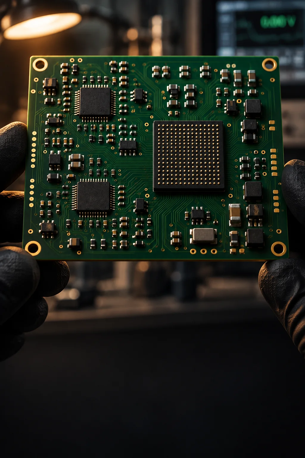
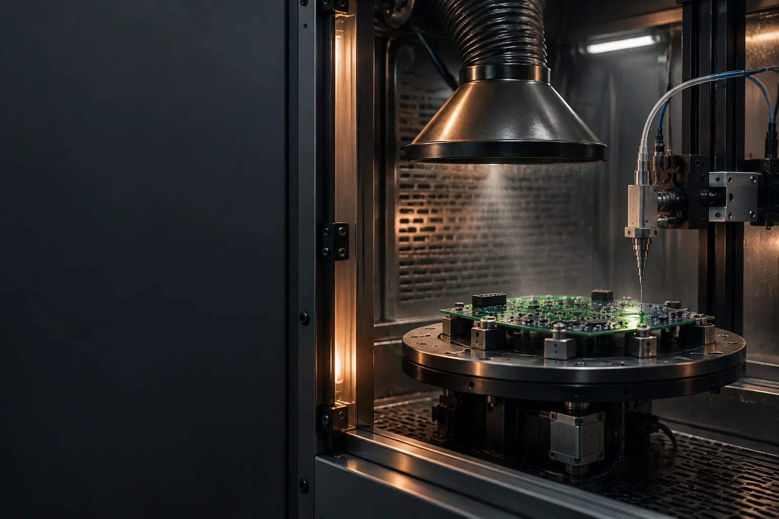
A conformal coating is a process, not a material. The film that survives ten years of humidity, salt fog and thermal cycling is the one applied over a clean, dry surface with the connectors and contact faces masked, cured to a measured thickness, and inspected under ultraviolet light before the assembly is packed.
Material comparison
Acrylic, polyurethane, silicone and parylene compared
Four chemistries cover almost every programme we quote. The comparison below is the table we work through with a buyer, because the deciding row is usually reworkability rather than dielectric strength.
| Property | Acrylic (AR) | Polyurethane (UR) | Silicone (SR) | Parylene (XY) |
|---|---|---|---|---|
| Cure mechanism | Solvent evaporation, air or oven | Two-part or moisture cure | Heat or moisture cure, solvent-free options | Vacuum deposition; no cure step |
| Temperature range | -40 to +125 C | -40 to +130 C | -55 to +200 C | -200 to +150 C |
| Dielectric strength | 300-500 V/mil | 400-900 V/mil | 400-700 V/mil | 5000-7000 V/mil |
| Chemical resistance | Weak against solvents and fuels | Good against fuels, oils and solvents | Good in general, weaker against solvents | Excellent against nearly every common chemistry |
| Reworkability | Easy; solvent removable | Difficult; needs heated solvent or abrasion | Easy; cut back and re-coated | Very difficult; abrasive removal plus re-deposition |
| IPC-CC-830B relevance | Type AR, the general-protection baseline | Type UR, specified where solvent resistance matters | Type SR, specified for wide temperature range | Type XY, specified where a pinhole-free film is required |
| Typical cured thickness | 30-130 um | 30-130 um | 50-210 um | 10-25 um |
| Moisture barrier | Moderate | Good | Moderate to good | Best available at any thickness |
| Application method | Selective spray, brush or dip | Selective spray, brush or dip | Selective spray, brush or dip | Vapour deposition in a vacuum chamber |
| UV traceability | Fluoresces; coverage is inspectable | Fluoresces; coverage is inspectable | Fluoresces; coverage is inspectable | No tracer; coverage proven by process record |
| Re-coat and repair | Re-coats cleanly over itself | Needs surface preparation before re-coat | Re-coats cleanly over itself | Stripped locally, then re-deposited in the chamber |
| Relative cost | Lowest | Low to moderate | Moderate | Highest, by a wide margin |
How coating is run
Clean, mask, cure and measure, in that order
The coating is only as good as the surface under it
A coating over flux residue, fingerprints or a hygroscopic layer traps the contamination instead of sealing it out, and the failure appears later as electrochemical migration between adjacent conductors. Assemblies are cleaned and dried to an ionic contamination limit before coating: 1.56 ug NaCl per square centimetre at Class 2 and 0.78 ug at Class 3, verified per lot rather than assumed. Boards that were handled after cleaning go back through the wash, because the whole point of the measurement is that it is taken on the surface the coating will actually touch.
Masking is specified in a document, not decided at the bench
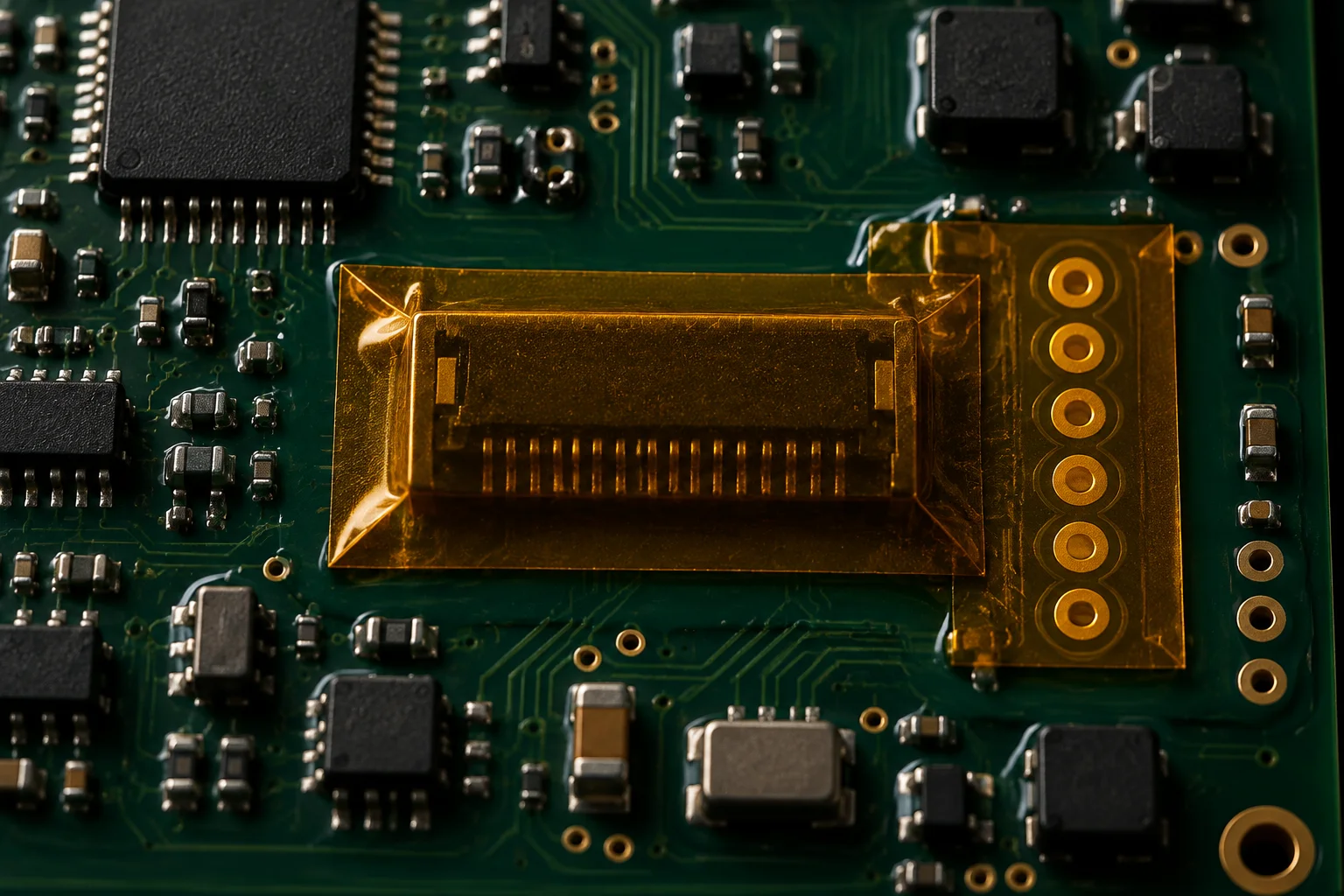
Every programme carries a coating drawing that lists each keep-out area, the masking method and the tolerance on the mask boundary. Connectors, card-edge fingers, press-fit tails, test points, sensor ports, threaded inserts and grounding studs are all named individually, with the reason recorded beside each one. Where a mask is applied by tape, the boundary is held to plus or minus 0.5 mm so a re-run of the same part number produces the same board rather than a slightly different one.
Cure, thickness and coverage are all measured
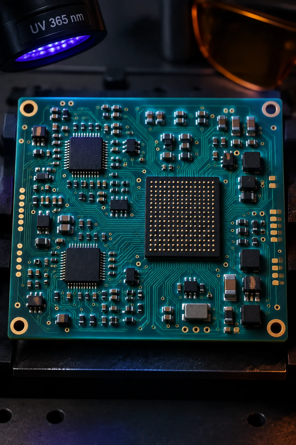
Spray parameters, booth temperature and cure schedule are recorded per batch, and film thickness is measured on a coupon that travels with the boards because measuring the assembly itself is destructive. Coverage is inspected under ultraviolet light on 100 percent of acrylic, polyurethane and silicone assemblies, which is what catches the shadow behind a tall component that a spray pass missed. Parylene has no tracer, so its coverage rests on the deposition record and a measured witness coupon.
Keep-out and masking
Where the coating is not allowed to go
Nine keep-out groups are checked on every coating drawing. Each one is a place where a functional surface, a contact face or a measurement path would be changed by a film measured in microns.
Connector contact cavities
Mating faces are booted or taped so no coating enters the contact cavity. A coated contact face raises the mating force and the contact resistance, and the fault appears as an intermittent connection long before it appears as a measurement.
Card-edge fingers and press-fit tails
Masked with a 0.5 mm overhang onto the laminate. Coating on a press-fit tail changes the interference fit and pushes the insertion force outside the 60-120 N per pin window, which damages the plated barrel rather than the pin.
Test points and probe pads
Left bare so a probe can penetrate the pad. A film only a few microns thick is enough to raise contact resistance and produce false failures in circuit, which costs more in diagnostic time than the masking costs to apply.
Relays, buzzers and open-contact devices
Not coated at all. A film on a contact face causes intermittent operation, and a film across the housing seam can seal a vent path that the device needs in order to switch cleanly at its rated load.
Pressure, humidity and gas sensor ports
Ports and diaphragms are taped. A blocked port changes the measurement outright, and a coated diaphragm changes its compliance, which shifts the calibration even when the port itself stays clear.
Optical windows, LEDs and photodiodes
Masked because a film changes the refractive index at the interface and narrows the emission angle. The board still passes electrical test, then fails an optical acceptance check at the customer's line.
Battery contacts and fuse clips
Masked so the coating cannot act as an insulator under a spring contact or as a thermal barrier across a fuse clip. Either failure mode appears as a voltage drop under load rather than as an open circuit.
Heatsink holes and threaded inserts
Plugged so the fastener torque stays inside the logged 0.4-4.0 Nm band and the coating cannot creep under the washer. Coating in a thread also changes the effective thread depth and the clamp load on the device.
Grounding studs and chassis bonds
Left bare so the bond stays metal to metal. A coated stud can still show DC continuity through the fastener while failing a 25 A bond check, which is exactly the fault that shows up as an EMC problem rather than a coating problem.
Macro record
Coverage under ultraviolet light
The UV tracer turns the film into something a camera can judge, which is the only practical way to inspect a coating that is transparent in visible light.
Buyer questions
Material choice, coverage evidence and rework after coating
It follows from the environment, the inspection method and the rework plan rather than from a preference. Acrylic is the cheapest and the easiest to rework but has the weakest solvent resistance. Polyurethane adds fuel, oil and solvent resistance and is harder to remove. Silicone holds its properties from minus 55 to plus 200 degrees Celsius but is the least resistant to solvents. Parylene is deposited in a vacuum at 10 to 25 microns, is pinhole-free and protects almost anything, and costs several times more with abrasive removal only. Where a programme expects rework, the coating choice is usually acrylic or silicone for that reason alone.
Three ways, used together. The acrylic, polyurethane and silicone families carry a UV tracer, so coverage is inspected under ultraviolet light on every coated assembly rather than on a sample. Film thickness is measured on a coupon that travels with the batch, because a measurement on the board itself is destructive. Parylene has no tracer, so coverage is proven by the process record: chamber load, deposition cycle and a witness coupon measured after the run. Where the specification names IPC-CC-830B, that is the qualification we test against and quote on the certificate.
Yes, up to a point, and the coating material decides where that point is. Acrylic and silicone are cut back locally with a scalpel and a solvent swab, the joint is reworked, and the area is re-coated and re-inspected under UV. Polyurethane needs a heated solvent or controlled abrasion and is normally removed in a defined repair window rather than a spot. Parylene has to be abraded away and then re-deposited in the chamber, so a repair on a parylene build is a production operation rather than a bench operation, and the rework record is attached to the serial number.