Facility / Bayan Lepas Free Industrial Zone
Inside the Factory
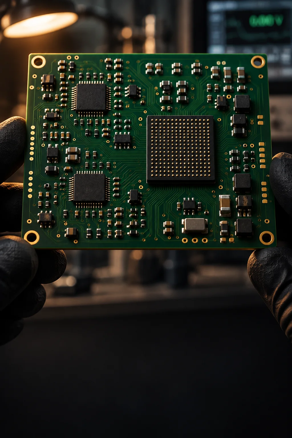
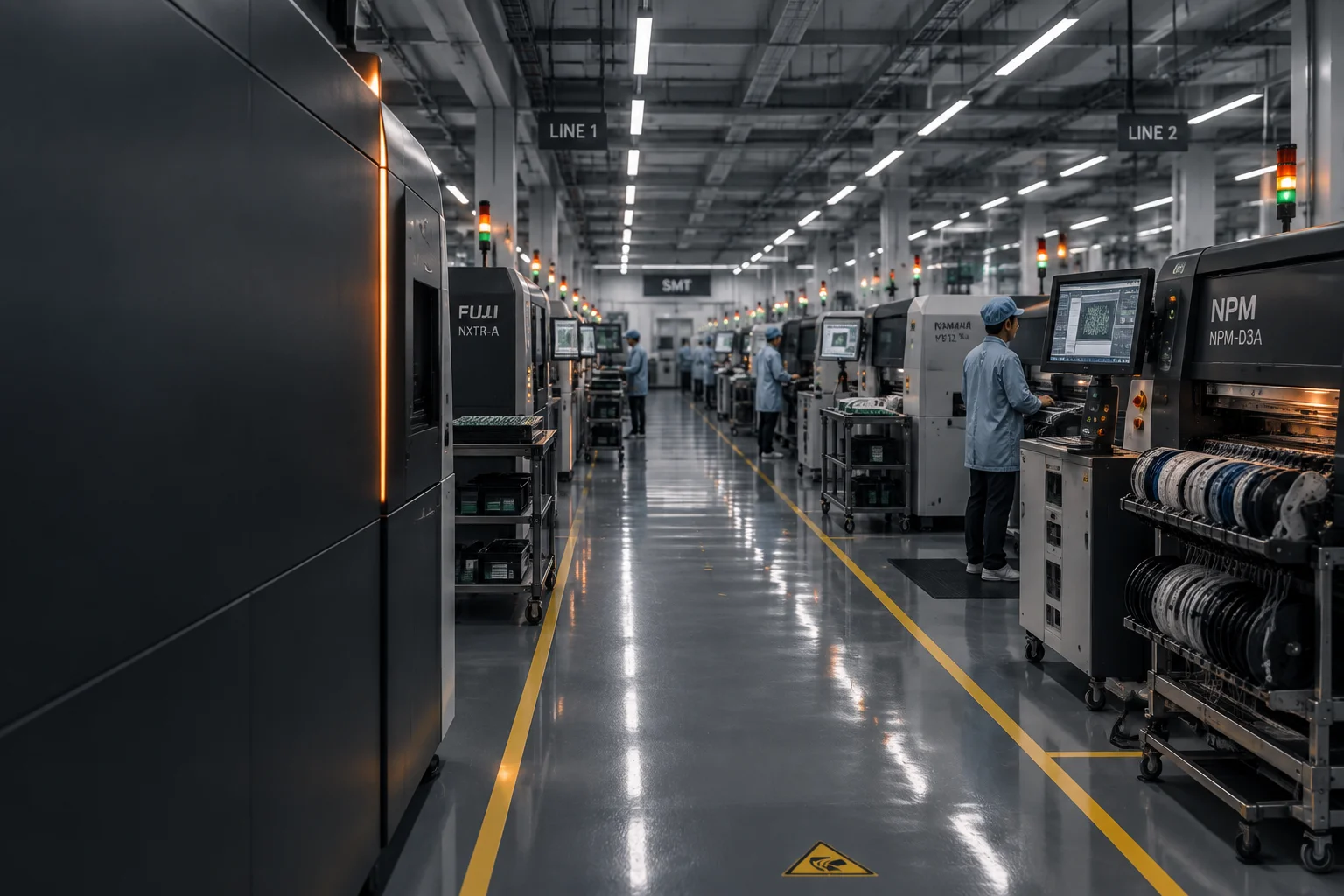
Six SMT lines, three wave lines and one selective-soldering cell sit inside 4,100 m² of ESD-controlled production area. This page lists the equipment classes, the capacity envelope they produce and the environment controls that keep component damage out of the process.
Equipment and capacity
What is installed, what it holds, and how it is monitored
Equipment is listed by class rather than by machine label, because a buyer is buying a process window: placement rate, pitch, board envelope and the inspection that follows each operation. Capacity figures are the envelope the lines can produce at the stated shift pattern, not a measured output.
| Equipment or area | Class | Specification | Capacity or monitoring |
|---|---|---|---|
| SMT lines | 6 lines | 3 high-speed chip-shooter lines plus 3 flexible high-mix lines | Two shifts, five days, with a third shift used for peak ramps |
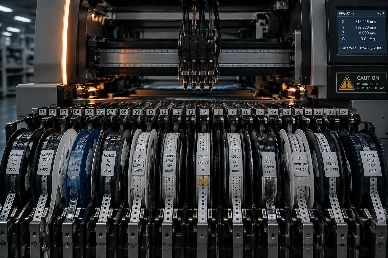
| Chip-shooter placement | High-speed | 40,000-80,000 CPH on the high-volume lines | Smallest chip placed is 01005 (0.4 × 0.2 mm) |
| High-mix placement | Flexible | 0.35 mm leadless and 0.4 mm leaded pitch at ±15-25 µm | Fine-pitch, odd-form and connector work |
| Board handling | Conveyor and magazine | Board thickness 0.4-4.0 mm; 1 to 32 incoming layers | Panel envelope up to 510 × 460 mm |
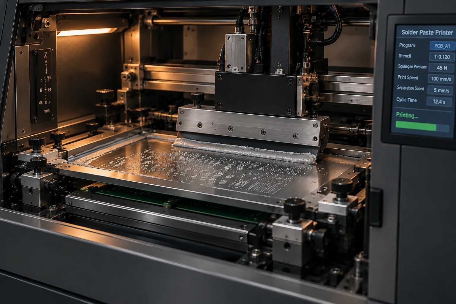
| Stencil printing | In-line printer | 100 µm, 120 µm and 150 µm foils | In-line SPI on 100% of printed boards |
| Reflow ovens | 10-zone forced convection | SAC305 at a 217 C liquidus, peak held at 235-245 C | Profile verified per paste lot and logged per panel |
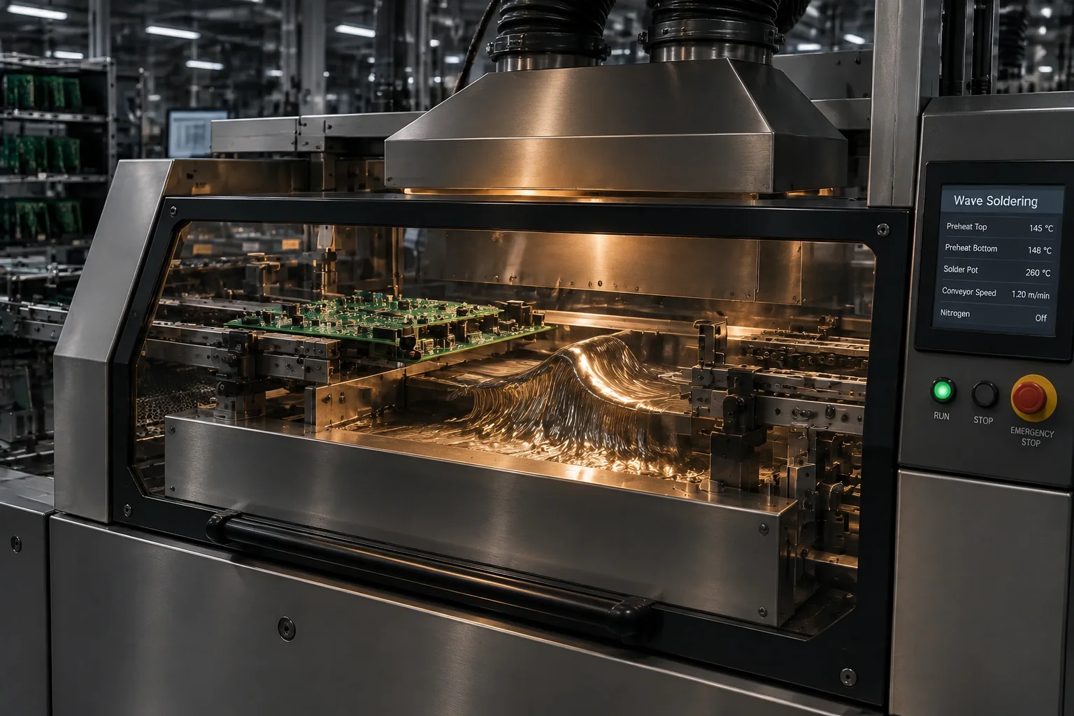
| Wave soldering | 3 DIP lines | Pot temperature 250-265 C with pallet support | First-off plus hourly coupons on each line |
| Selective soldering | 1 cell | Dedicated nozzle with soaked preheat for heavy joints | Used for connectors, press-fit and thick copper planes |
| AOI | In-line optical | Programmed to the IPC-A-610 class on the drawing | 100% coverage on every SMT build |
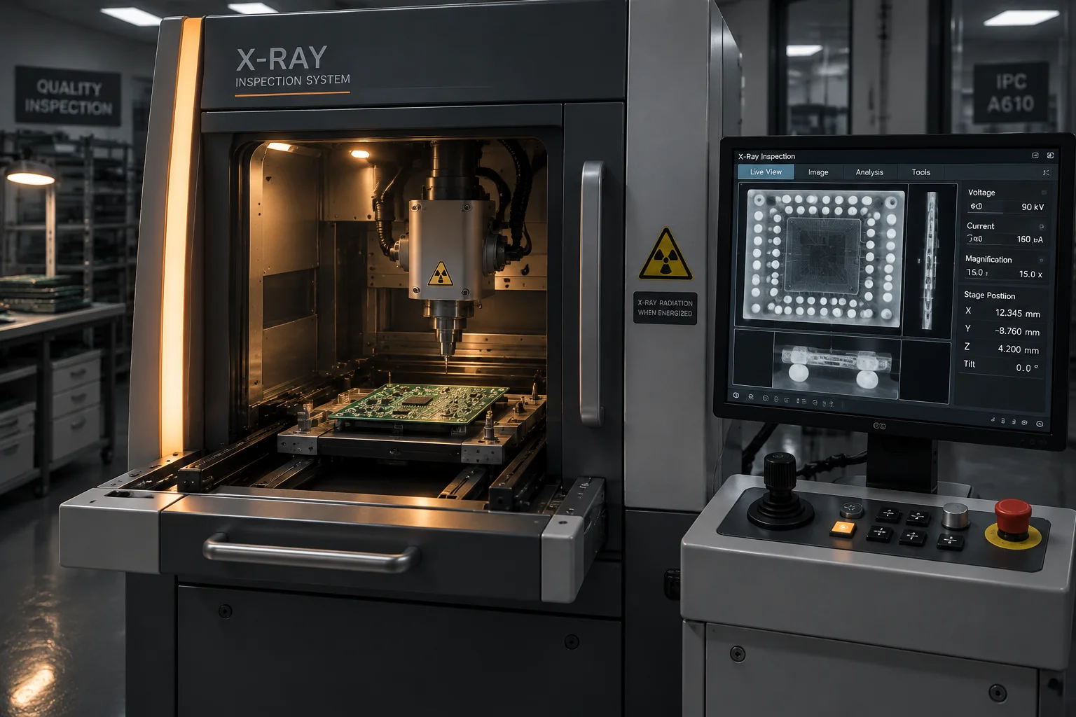
| X-Ray | 2D and 3D | Void measurement on hidden joints | Every BGA and QFN, images retained per serial |
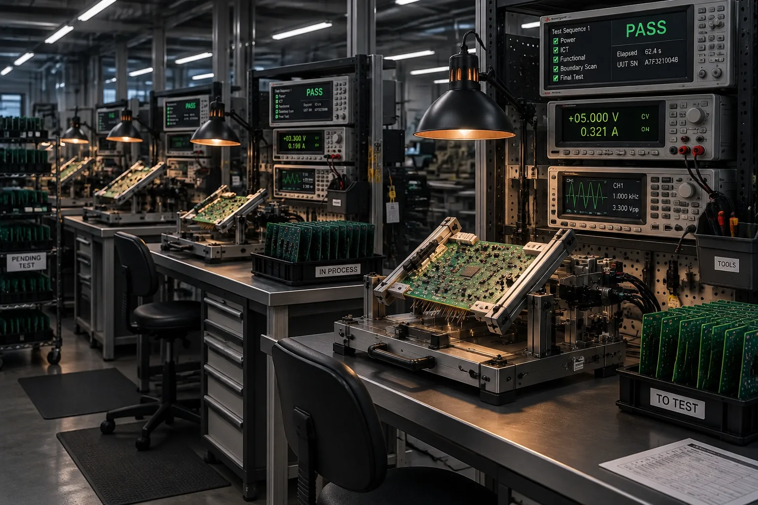
| ICT | Bed-of-nails fixture | Fixture cost band 2,000-50,000 USD, 4-8 weeks lead time | Program developed in house against your netlist |
| Flying probe | Fixtureless | Roughly 3-10 USD per board with no fixture cost | Used for prototypes and low-volume programmes |
| Functional test | Custom fixture | Fixture cost band 1,000-10,000 USD, 1-2 weeks lead time | 100% or sampled, per the programme test plan |
| Placement capacity | 6 SMT lines | Up to 1.6 million placements per day at chip-shooter rates | Zero MOQ on prototypes, MOQ 1 panel on production |
| Floor area | 6,400 m² total | 4,100 m² ESD-controlled to ANSI/ESD S20.20 | Temperature and humidity logged continuously |
| Headcount | ~240 staff | Engineering, test development, quality and planning on site | Three shifts across the assembly floor |
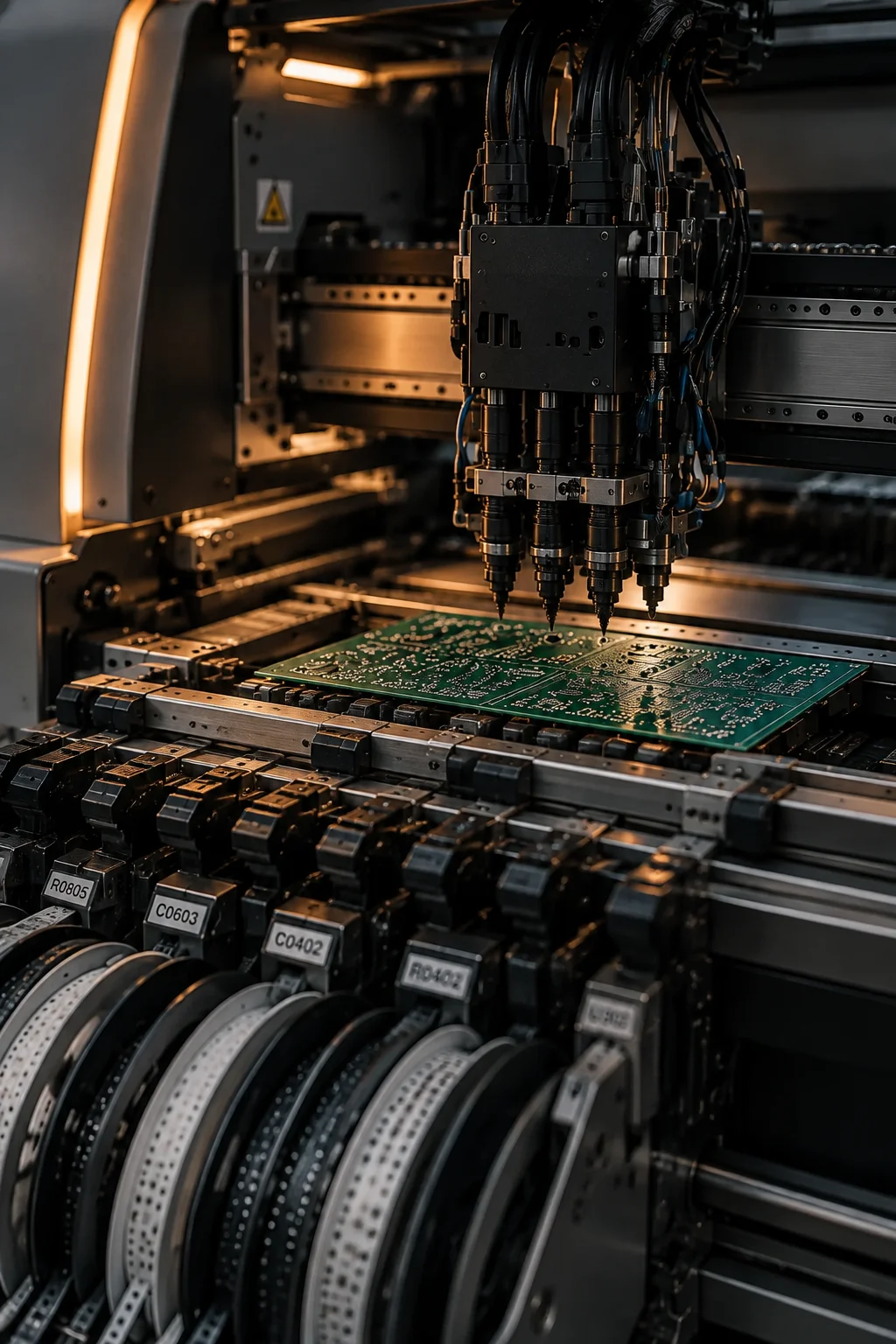
Equipment gallery
The cells a board actually travels through
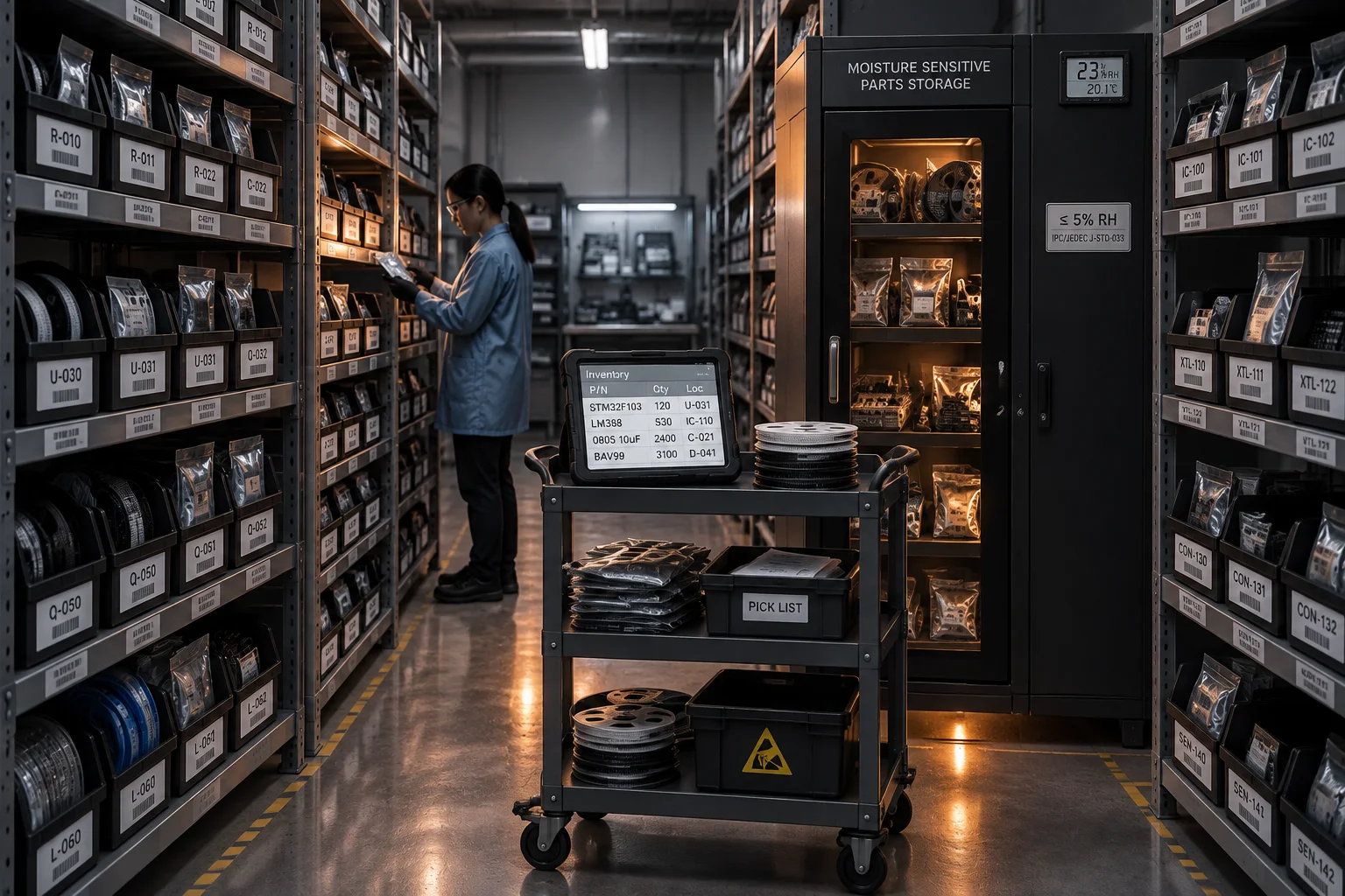
Six views along the production route, in the order a panel follows from print to final test.
How the floor is run
Capacity, changeover and maintenance on a mixed high-volume, high-mix floor
Line assignment by board class
High-volume programs with a stable BOM run on the three chip-shooter lines, where the placement rate does the work and the setup cost is amortised over a long run. Boards with fine pitch, connectors, shielding or odd-form parts run on the high-mix lines, where feeders and nozzles change more often but the process window is wider. A panel never moves between the two classes without the AOI program, the reflow profile and the first-article record being requalified on the destination line.
Changeover as a controlled process
Feeders are loaded and verified offline against the BOM before the previous job finishes, and the stencil, the AOI program and the test fixture are staged at the line. The first article then goes through SPI, AOI and X-Ray before the line is released, which is the step that keeps a high-mix week from turning into a scrap week. Recent high-mix changeovers average 34 minutes from last board to first article.
Maintenance and calibration
Reflow ovens are profiled per paste lot, printers are checked against the SPI baseline at the start of every shift, and X-Ray, test fixtures and torque drivers sit on a 12-month calibration cycle with the status recorded in the traveller. Solder pots are checked daily for temperature and chemistry, because a wave pot drifts slowly enough that the first sign is usually a joint defect rather than an alarm.
Line utilisation
Availability, performance and quality for one measured month
OEE is the product of three ratios, so a number that looks healthy on availability alone is easy to check. The block below is the format returned to a customer when a programme needs the loading evidence.
window        December 2025, 3 chip-shooter and 3 high-mix lines
planned       2 shifts x 5 days, 392 scheduled machine hours
availability  92.4%  unplanned stops and maintenance removed
performance   88.1%  actual rate against the rated rate
quality       99.4%  first-pass, no rework counted as good
oee           80.9% = 0.924 x 0.881 x 0.994
changeover    34 min average on the high-mix lines
utilisation   86.2% of planned hours booked to customer work
scrap        0.9% of placements, screened by AOI and X-Ray
wip          under 1 shift of work in front of the lines
ESD and environment control
The nine controls that protect components before soldering
Static damage does not announce itself: a latently damaged input can pass every inspection gate and fail in the field. These are the control limits the floor is held to, with the interval each one is checked at.
| Control | Limit held | How it is monitored |
|---|---|---|
| Temperature | 22 ± 3 C across the assembly hall | Continuous logging with an alarm outside the band |
| Relative humidity | 30-60% RH, the band that keeps paste behaviour stable | Continuous logging per zone, reviewed daily |
| Flooring | Conductive tile between 1 × 10⁶ and 1 × 10⁹ ohm | Resistance measured at fixed points on a monthly cycle |
| Wrist straps | 1 MOhm series resistance at every bench and line position | Tested at the start of each shift, logged per operator |
| Footwear and heels | Conductive footwear inside the EPA boundary | Tested at the gate on entry, with a daily record |
| Ionisers | Balanced to within ±35 V offset at the manual stations | Offset verified quarterly and after any emitter cleaning |
| Moisture-sensitive parts | Dry storage below 5% RH with floor life tracked per J-STD-033 | Cabinet logs plus a floor-life clock on every reel opened |
| Baking | 125 C for 24 h for parts at MSL 3 and above that exceeded floor life | Bake log retained with the panel record |
| Calibration | Test equipment, X-Ray and torque drivers on a 12-month cycle | Status recorded on the traveller before a job is released |
Buyer questions
Audits, growth and changeover on this floor
Yes. A customer audit is normally half a day: the ESD floor, one line running your board class, the inspection cell, the MSD store and the calibration records, followed by the documentation sample. Remote audits are run the same way over a video link with the camera walked to the equipment, and we will re-run an audit after a process change rather than showing the same recording twice. Travel and accommodation are yours; the audit itself is not chargeable.
Capacity is planned at line level, not at plant level, so a ramp is handled by moving the programme to a second line of the same class and duplicating the setup: stencil, AOI program, reflow profile and test fixture. Production above roughly 8,000 units per month on a dense board normally needs two lines on the same part number, and we ask for a 12-week demand view so the second line is qualified before the ramp rather than during it.
A high-mix line runs small batches, so the setup is controlled like a process: feeders are loaded and verified offline against the BOM, the stencil and the AOI program are staged before the previous job ends, and the first article goes through SPI, AOI and X-Ray before the line is released to run. Recent high-mix changeovers average 34 minutes, and the first-pass yield on those lines is held inside the same published figure as the high-volume lines.