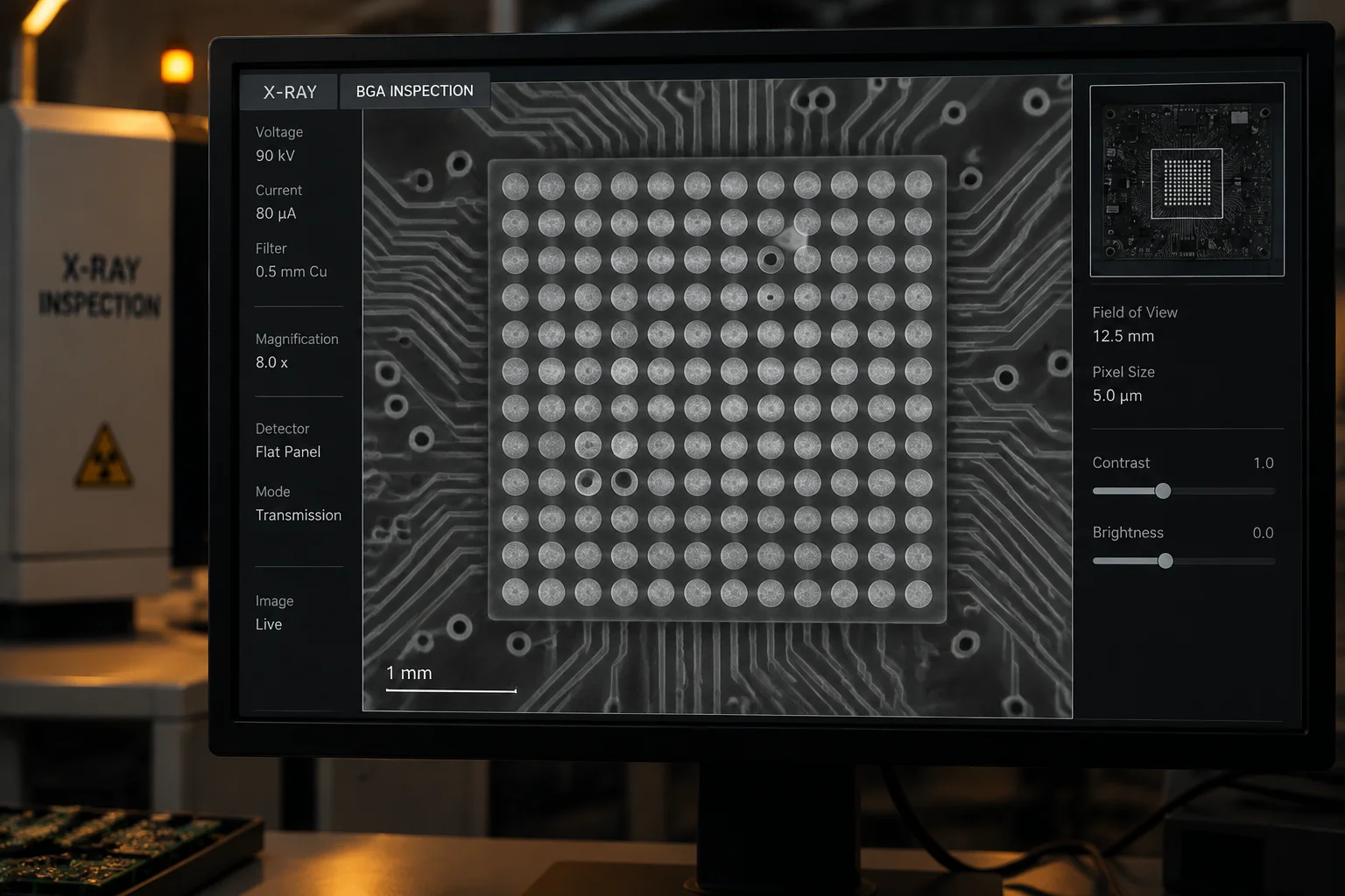
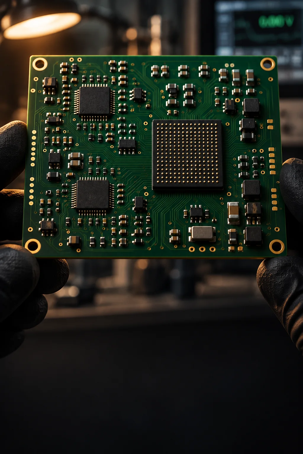
Optical inspection head scanning a populated board on a conveyor, with a transmission image of a ball grid array on the monitor beside it

Capability / Inspection and verification

AOI and X-Ray Inspection: What Each Method Can and Cannot Catch

Every inspection method has a blind side, and a programme's real escape risk is set by the defects that fall into it. Optical inspection reads surfaces; transmission X-ray reads structure; neither reads behaviour. This page sets out the eight defect classes we screen for, the method that catches each, and the acceptance limit that decides pass or fail.

Electrical test

100% AOI coverage on SMT builds
<10% BGA void at Class 3
0.06% published field return rate

Defect atlas

The defect atlas: the escape modes and the method that catches each

These are the eight defect classes that account for almost every solder escape we are asked to investigate. Each card names the primary method, the limit that decides the call, and what remains exposed after that method has run.

DEF-01 / Tombstoning

Tombstoning

Caught by
Post-reflow AOI
Decided at
One end lifted clear of the pad

A passive that stands on one termination changes height and silhouette, so optical inspection sees it reliably on 0402 and above. Escape risk rises sharply when the part sits under a shield can or inside a connector recess, where only functional test will notice the open circuit.

DEF-02 / Bridging

Bridging

Caught by
Post-reflow AOI, confirmed by in-circuit test
Decided at
Any solder between adjacent conductors

Exposed leads and pads show a bridge clearly, and 0.4 mm leaded pitch is well inside optical resolution. A bridge underneath a package body is invisible to optics, so the electrical test step carries the coverage there and a net-level short is what proves it.

DEF-03 / Insufficient solder

Insufficient solder

Caught by
Post-reflow AOI by volume estimate
Decided at
Fillet below the Class 2 minimum

A fillet that is thin but continuous passes an optical volume check, which makes this the quietest escape in the atlas. On a heavy thermal pad the thin joint survives the bench, then cracks after a few hundred thermal cycles, so the defence is paste volume control at printing rather than inspection after reflow.

DEF-04 / Missing or misplaced

Missing or misplaced component

Caught by
Pre-reflow optical, then post-reflow AOI
Decided at
Absent body, or offset beyond 25% of the pad

Placement faults are the cheapest defects to catch, because they exist before the joint is formed and a reflow pass has not yet been spent on them. A part shifted onto one pad but still soldered is the harder case, since it can pass both optical and electrical screening and fail a vibration or drop test later.

DEF-05 / Wrong polarity

Wrong polarity

Caught by
Post-reflow AOI against the polarity marking
Decided at
Cathode band or pin-1 marker reversed

Optical inspection resolves polarity well down to 0402 because it reads the marking rather than the solder. The escape case is a diode or electrolytic capacitor in a package where the marking is a small chamfer, and the failure then appears as a reversed rail rather than as a joint defect.

DEF-06 / BGA void

BGA void

Caught by
3D CT X-Ray, measured per ball
Decided at
Under 25% Class 2, under 10% Class 3

Voiding is a reflow profile and paste chemistry outcome, and it is invisible from above the package. The commercial problem is the ball that sits just inside the acceptance band: it passes by rule, then grows under thermal cycling until the joint separates within the warranty period.

DEF-07 / Head-in-pillow

Head-in-pillow

Caught by
3D CT X-Ray, then dye-and-pry on a sample
Decided at
Ball in contact without coalescence

The ball rests on the paste without merging, so the joint conducts under probe pressure and separates once it sees a few temperature cycles. 2D X-ray shows a joint that looks present, which is why this class is checked in three dimensions on Class 3 and safety-related programmes.

DEF-08 / Barrel fill

Insufficient barrel fill

Caught by
X-Ray fill estimate, confirmed by cross-section
Decided at
100% vertical fill at Class 3, 75% at Class 2

Fill level inside a plated hole is hard to measure optically, and a partial fill still conducts, so it escapes every continuity test and every visual check. The confirming evidence is a microsection taken from the lot, with a minimum of two locations recorded per lot at Class 3.

Method and limit

Inspection method, coverage and the limit that decides the call

Fourteen inspection methods are available in this facility. Where a row carries a standard, that standard is the limit quoted on the inspection plan rather than a general reference.

Inspection method, coverage applied and detection limit - IPC-A-610H Class 2 and Class 3
Method Coverage applied Detection limit Governing limit or standard
Solder paste inspection 100% of prints on production builds Deposited volume outside 80-120% of the aperture Aperture area ratio above 0.66
Pre-reflow optical 100% of SMT builds after placement 0402 and above reliably; 01005 with the high-resolution lens IPC-A-610H Class 2 target condition
Post-reflow optical 100% of all SMT builds Fillet length and presence; judgement drops below 0.35 mm pitch IPC-A-610H Class 2 and Class 3
Two-dimensional X-Ray Every BGA and QFN, plus a sample on legacy through-hole work Ball presence and bridging; void depth is not measurable IPC-7095 reference for voids
Three-dimensional CT X-Ray Every BGA on Class 3 and safety-related programmes Void percentage per ball and head-in-pillow separation Under 25% Class 2, under 10% Class 3
Bench visual inspection 100% at Class 3, sampling at Class 2 Workmanship above roughly 0.4 mm leaded pitch IPC-A-610H, CIS-certified inspectors
UV coating inspection Every coated assembly Coverage and keep-out compliance, not adhesion or cure state IPC-CC-830B qualification reference
Microsection Minimum 2 locations per lot Barrel fill, annular ring and intermetallic thickness IPC-6012 Class 3: 25 um minimum plated copper
Ionic contamination Once per lot by ROSE or ion chromatography Residue expressed as NaCl equivalent per square centimetre 1.56 ug Class 2, 0.78 ug Class 3
Dye-and-pry Sample after thermal cycling on BGA programmes Cracked balls and non-coalesced head-in-pillow joints IPC-9708 test method
In-circuit test 100% where the volume band justifies a fixture Continuity, shorts and value against the netlist CAD netlist comparison
Flying probe 100% on high-mix and prototype volumes The same electrical facts, without fixture pressure on the joint CAD netlist comparison
Functional test 100% where the test plan specifies it Behaviour at one defined operating point Customer limit table with stated conditions
Hipot on coated assemblies 100% on mains-connected medical and energy builds Dielectric breakdown or flashover across the barrier 4000 V AC for 1 minute at 2xMOPP, 250 V
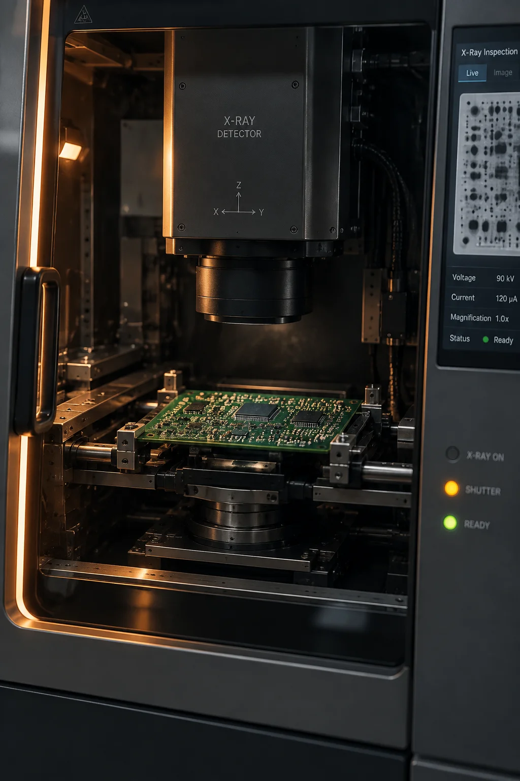
Vertical X-ray inspection system with a board stage, leaded viewing window and transmission image displayed on the operator screen

How inspection is run

Recipes, review discipline and the evidence that leaves with the lot

Recipes are built from the CAD data, not from a golden board

An optical recipe programmed from a known-good assembly inherits that assembly's defects. We build the program from the CAD placement data so the expectation is generated rather than measured, and then confirm it against the first article. Library parts carry their own inspect windows, which keeps a 01005 passive and a 33 mm connector from sharing one tolerance. Every recipe revision is versioned, so the images retained against a serial number can be traced to the program that judged them.

False calls are reviewed, not tuned away

The tempting fix for a noisy optical line is to widen the window until the false calls stop, which quietly widens the escape band as well. We review the false-call Pareto weekly and change the library part or the lighting rather than the accept threshold, and any threshold change is recorded as a recipe revision with a reason. On a Class 3 programme the accept threshold is not a tunable at all, because the rejection band widens from 2-5% at Class 2 to 8-15% at Class 3 and the physics does not move with the number.

Every escape is fed back into the recipe

When a defect reaches the field, or is caught late by functional test, the image set for that serial number is reopened and the recipe is asked why it passed. The answer is usually a lighting angle, a library window or a keep-out that hid the joint, and it becomes a permanent change rather than a note. That loop is what holds the published field return rate at 0.06% while the mix of packages on the line keeps getting denser and smaller.

Four-way coverage

Optical, transmission, visual and electrical coverage side by side

The four methods answer different questions about the same joint. Presented together, the table shows why they are additive rather than alternative, and why removing one moves cost into returns rather than into savings.

Coverage comparison across optical, transmission, visual and electrical methods
Comparison Optical AOI X-Ray Visual inspection Functional test
Sees Surface features within line of sight Internal structure by transmission Whatever the eye resolves at the bench Electrical behaviour against limits
Blind to Under a BGA, can, body or thermal pad Electrical function and marginal wetting Features below 0.4 mm leaded pitch Anything structural that still functions
Coverage here 100% of SMT builds Every BGA and QFN 100% at Class 3, sampling at Class 2 100% where the test plan specifies it
Cycle time 5-15 seconds per board 30 seconds to several minutes per board 30-120 seconds per board 30 seconds to 5 minutes per board
Cost per board $0.20-0.50 $1-5 in 2D, $5-20 in 3D $0.10-0.25 $1-25 depending on test level
Catches Bridging, tombstoning, polarity, missing part Void, ball integrity, barrel fill, head-in-pillow Workmanship, labelling and mechanical fit Wrong value in an identical package, and dead rails
Reference cited IPC-A-610H Class 2 and Class 3 IPC-7095 void acceptance IPC-A-610H with CIS-certified inspectors The customer limit table and its conditions
Escape left open Hidden joints and thin but continuous fillets Electrical failure with intact structure Fine geometry and sub-surface defects Marginal joints, drift and wear-out

Macro record

Three views of the defects the atlas describes

One transmission image and two optical macros, taken at the magnification the recipe actually judges at rather than at a marketing scale.

Grey-scale transmission X-ray image of a ball grid array showing voiding inside individual solder balls
Transmission image / BGA ball field Void measured per ball against the 10% Class 3 limit
Macro view of a small passive component standing on one end with the opposite termination lifted clear of its pad
Optical macro / tombstoned passive Height change is the signal the optical recipe reads
Macro view of a solder bridge joining two adjacent fine-pitch component leads
Optical macro / bridge at fine pitch Confirmed as a net short by in-circuit test

Buyer questions

Blind spots, void limits and escapes that survive the line

Get Quote Call Us
marker. Behaviour comes from inquiry-handler.js via data attributes — no inline JS, no onclick, no inline style (CSP: script-src 'self'; style-src 'self'). ============================================================================ --> marker. Behaviour comes from inquiry-handler.js via data attributes — no inline JS, no onclick, no inline style (CSP: script-src 'self'; style-src 'self'). ============================================================================ --> marker. Behaviour comes from inquiry-handler.js via data attributes — no inline JS, no onclick, no inline style (CSP: script-src 'self'; style-src 'self'). ============================================================================ -->