ACC-01 / Wetting
Wetting within one second
Solder wets the pad and the lead within 1 second of contact, with a visible feather edge. A non-wetting or dewetting surface is rejected and the joint is redone, never topped up.

Through-hole / wave, selective, press-fit
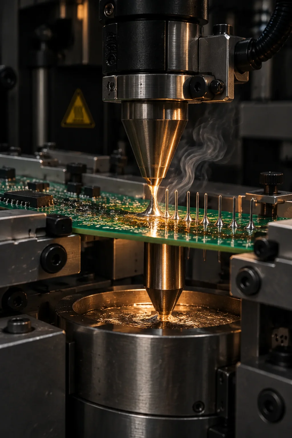
Three wave and DIP lines plus a single selective soldering cell handle axial parts, connectors, transformers and heavy power devices that cannot be reflowed. Solder pots run at 250-265 C with 3-5 second contact, and every barrel is checked for vertical fill against the Class 3 requirement of 100%.
Four soldering routes
The through-hole method is a cost and risk decision, not a preference. Pin count, board thickness, neighbouring SMD parts and connector mass each push the choice one way.
A spray or foam fluxer, topside preheat at 90-120 C and a chip wave followed by the main wave. The pot sits at 250-265 C, contact is 3-5 seconds and the conveyor runs 1.0-1.4 m/min. Above roughly 200 pins facing the same direction it is the cheapest route per pin at $0.02-0.04.
Drop-jet fluxing and a 3-6 mm single-point nozzle under a nitrogen blanket with oxygen held below 1,000 ppm. This is the route for connectors sitting a few millimetres from 0402 parts, for assemblies over 4.0 mm thick, and for a handful of pins where a wave would be waste.
Thermal-controlled irons run at 350-380 C with a 2-5 second dwell, used for repairs, single joints, and parts that cannot see either wave. Every operator is trained to the workmanship class on the drawing and records each joint against the board serial.
A compliant pin pressed at 60-120 N into a 0.6 mm minimum finished hole removes the thermal load entirely, which matters for backplane connectors and for boards that must survive repeated mating cycles without a rework allowance.
Capability table
Settings an inspector can confirm on the line, and the standard each limit comes from.
| Parameter | Method or tool | Capability | Governing standard |
|---|---|---|---|
| Through-hole grid | Wave and selective | 2.54 mm standard, 1.27 mm on request | IPC-2222 hole placement |
| Minimum finished hole | Wave and press-fit | 0.6 mm after plating | IPC-6012 Class 2 and 3 |
| Maximum assembly thickness | Wave | 4.0 mm; thicker boards route to selective | Barrel aspect ratio 8:1 |
| Solder pot temperature | Wave | 250-265 C, SAC305 or SnPb | J-STD-001 alloy control |
| Wave contact time | Wave | 3-5 seconds total in the solder | Profile per assembly |
| Conveyor speed | Wave | 1.0-1.4 m per minute with a 6-8 degree incline | Profile per assembly |
| Topside preheat | Wave | 90-120 C measured on the component side | Thermal shock limit 4 C/s |
| Flux deposition | Spray or foam fluxer | 1,000-1,500 ug/cm2 solids on the topside | J-STD-001 flux control |
| Selective nozzle size | Single-point selective | 3-6 mm nozzle, drop-jet fluxing | Process specification |
| Nitrogen blanket | Selective | Oxygen below 1,000 ppm in the solder zone | Dross and wetting control |
| Hand-solder tip temperature | Thermal-controlled iron | 350-380 C with a 2-5 second dwell | IPC-7711 and 7721 rework |
| Pin-in-paste | Stencil aperture plus reflow | 1:1 aperture with a 0.1-0.2 mm paste overprint | J-STD-001 paste control |
| Press-fit insertion | Compliant-pin press | 60-120 N per pin, no solder joint formed | Connector datasheet plus IPC-2222 |
| Barrel vertical fill | All through-hole joints | 75% minimum at Class 2, 100% at Class 3 | IPC-A-610 through-hole criteria |
Method comparison
The same joint can be made three ways at three different costs. This is the comparison the process engineer walks through with you before quoting.
| Selection criterion | Wave soldering | Selective soldering | Hand soldering |
|---|---|---|---|
| Best fit geometry | 200 or more pins facing one direction | A few connector rows among SMD parts | Single joints, repairs, odd-form parts |
| Thermal load on the board | Whole assembly sees the wave | Local, millimetre-scale heating | One joint at a time |
| Throughput | Continuous, panels per hour | Programme bound, 1-3 s per joint | Seconds per joint, operator bound |
| Typical cost per pin | $0.02-0.04 automated | $0.10-0.30 per board added | $0.05-0.10 manual at low volume |
| Solder mask and SMD proximity | Needs 2-3 mm keep-out from the wave | Works within a few millimetres of 0402 parts | No keep-out beyond iron access |
| Pallet required | Usually, for heavy or low-mass boards | Programmed fixture or bare support | None |
| Inspection method | Visual plus X-Ray sampling | Visual, with fill verified by X-Ray | 100% visual at Class 3 |
| Where it fails | Shadowing behind tall parts, thermal damage on thin boards | Slower on high pin counts, nozzle change cost | Operator variance, no statistical control |
Acceptance criteria
Eight criteria applied at the bench and again at final inspection. Each one has a number behind it, so a disagreement is settled by measurement.
ACC-01 / Wetting
Solder wets the pad and the lead within 1 second of contact, with a visible feather edge. A non-wetting or dewetting surface is rejected and the joint is redone, never topped up.
ACC-02 / Fillet
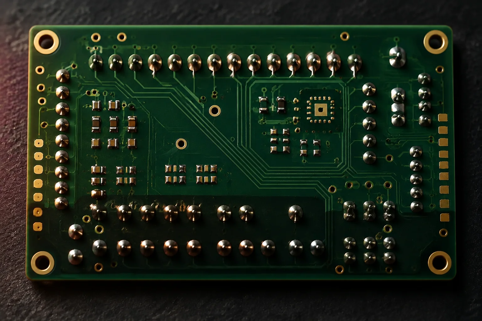
The fillet is concave on both sides of the lead and the contact angle stays below 90 degrees. Solder overlapping the land edge by more than 25% of the pad width is a defect.
ACC-03 / Barrel fill
Plated barrels must show 100% vertical fill for Class 3 and at least 75% for Class 2, measured from the topside land to the bottom land. Thermal vias are exempt by drawing note.
ACC-04 / Lead protrusion
A clinched lead protrudes 0.5-1.5 mm beyond the solder side pad, with a 30-45 degree bend and no crack at the knee. Longer leads are trimmed before soldering rather than after.
ACC-05 / Clearance
Sleeving and wire insulation stop at least 1.0 mm from the joint so the solder fillet forms on metal, not on plastic. Melted insulation is a defect even when the joint is electrically sound.
ACC-06 / Residue
No-clean processes leave no visible flux on the joint; where cleaning is specified, ionic contamination is verified at or below 0.78 ug NaCl/cm2 for Class 3 assemblies.
ACC-07 / Rework
A joint is reworked at most once. The pass is logged against the board serial with the operator, the iron temperature and the date, so a repeat failure is visible in the record rather than on the customer site.
ACC-08 / Thermal damage
No discoloured or measled laminate, no lifted pad and no cracked meniscus around the barrel. Any of the three scraps the assembly at Class 3, regardless of the electrical result.
Macro record
Questions
Selective soldering wins once through-hole parts share a board with surface mount devices on the solder side, when the assembly is thicker than 4.0 mm, or when only a handful of pins need solder. The wave is faster and cheaper above roughly 200 pins that all face the same direction.
Yes, provided the SMT side is completed and reflowed first. Selective soldering with a 3-6 mm single-point nozzle and a nitrogen blanket lets us solder a 2.54 mm connector row within a few millimetres of 0402 parts without reflowing them a second time.
We do. Compliant pins are pressed at 60-120 N per pin into a 0.6 mm minimum finished hole, which removes the thermal load from the connector and the board entirely. Press-fit is common on backplane and power connectors that must survive repeated mating.
Seven fields. A process engineer replies within one working day.
Seven fields. A process engineer replies within one working day.
Seven fields. A process engineer replies within one working day.