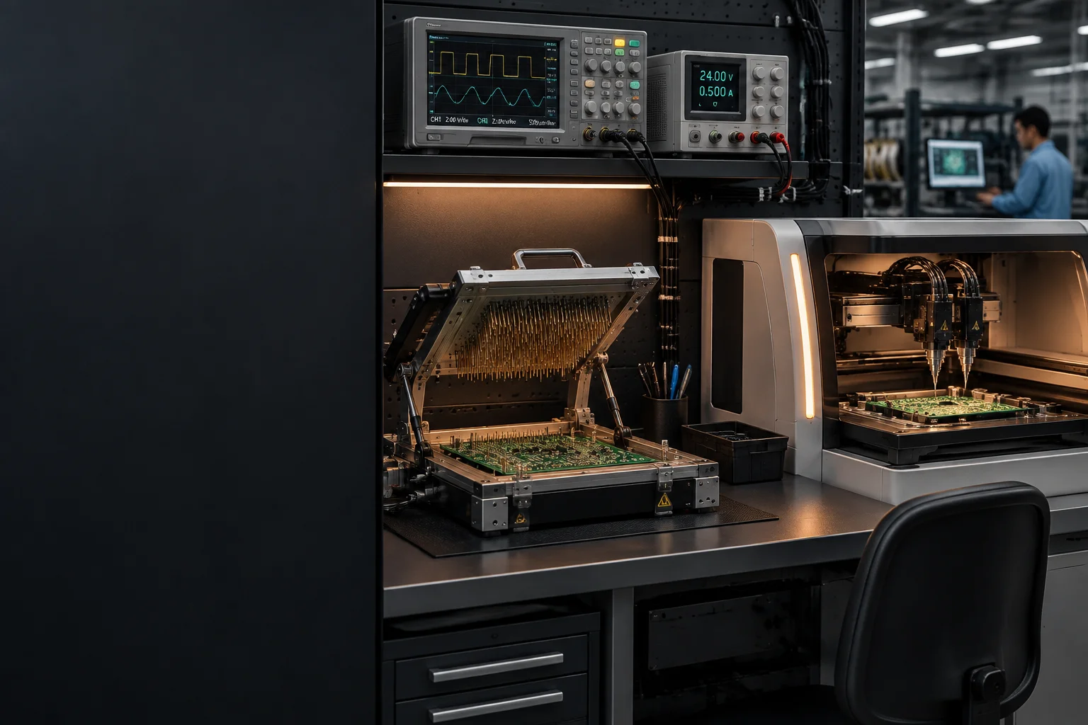
Test fixture loaded with a populated board on a bench, probe plate raised and instrument rack lit behind it

Capability / Test engineering

Test Engineering: ICT, Flying Probe and Functional Test

A test strategy is an economic decision before it is an electrical one. The board that leaves the line has already been through 100% AOI and X-Ray on every hidden joint, so the question the test engineer answers is narrower and harder: which defects can still escape, and what is it worth to close each one.

Inspection coverage

5-30 s in-circuit test per board
30 s-5 min functional test per board
1.0 mm test pad on a 2.54 mm grid

Coverage matrix

Test coverage matrix: what each method proves and what it cannot see

Thirteen methods sit between the printer and the shipping carton. Each row states the question the method answers, the defect class it is blind to, and the cost and lead time it carries, so the strategy can be costed before it is chosen.

Test and inspection coverage - 13 methods - cost and lead time as industry-typical bands
Test type What it proves What it cannot see Typical cost Lead time to first run
Solder paste inspection Deposited paste volume and alignment against the aperture, before any component is placed Placement errors, and anything that happens during reflow $0.10-0.30 per board Inline, no added lead time
Pre-reflow optical Component presence, orientation and value marking before the joint exists Joint quality, because there is no joint yet $0.15-0.35 per board Inline, no added lead time
Post-reflow optical Tombstoning, bridging, missing parts, wrong polarity and insufficient solder fillets Anything under a BGA, a shielded can or a connector body $0.20-0.50 per board Inline, no added lead time
Two-dimensional X-Ray Ball presence, bridging under a package, barrel fill on plated holes Void depth, head-in-pillow, and electrical function $1-5 per board Inline, recipe setup 2-4 h
Three-dimensional X-Ray Void percentage per ball and head-in-pillow through the package Electrical function, and marginal wetting that is still contiguous $5-20 per board Inline, CT recipe 4-8 h
Bench visual inspection Workmanship, labelling, mechanical fit and packaging Features below 0.4 mm leaded or 0.35 mm leadless pitch $0.10-0.25 per board Inline, no added lead time
UV coating inspection Coating coverage, keep-out compliance and edge definition Adhesion, thickness uniformity and cure state under a shadow $0.20-0.40 per board Inline after the cure pass
In-circuit test Continuity, shorts, wrong value, missing part, polarity and boundary-scan pin opens Marginal joints that conduct under probe pressure, RF behaviour and drift $0.50-2.00 per board after the fixture 4-8 weeks for the fixture
Flying probe The same electrical facts as in-circuit test, at any volume, without a fixture High node counts economically, and joints that fail only under mechanical stress $3-10 per board Hours of programming, no fixture
Boundary scan Interconnect continuity and IC pin opens through the scan chain Nets outside the chain and every analogue section $0.10-0.40 per board 1-2 weeks for chain validation
Functional test, board level Behaviour against written limits at one defined operating point Marginal timing, temperature extremes and long-term drift $1-10 per board 1-2 weeks for the fixture and program
Functional test, system level Whole-product behaviour with firmware, interfaces and enclosure Wear-out mechanisms and any parameter that moves over months $5-25 per board 2-4 weeks including the harness
Thermal cycling and stress screen Intermittent joints and thermal margin revealed by cycling Random defects at low volume, and anything not stressed by the profile $2-15 per board 4-8 weeks to define the profile

How the strategy is built

Where test cost lands, and why the sequence matters

The cheapest gate runs first

Sequence is chosen by cost per defect caught, not by prestige. Solder paste inspection costs cents and catches a printing fault before a hundred hidden joints are made from it. Optical inspection follows at under half a dollar and removes most visible faults before any fixture is loaded. Electrical test is the expensive gate, so it should only ever be asked to catch what the cheap gates physically cannot, which is why the coverage matrix names the blind spot of every method rather than its strengths.

Test access is a layout decision, not a fixture decision

A 1.0 mm test pad on a 2.54 mm grid costs nothing at layout and a revision later. We review every design for probe access on both sides, for a 3 mm clearance ring around tall components, and for via tenting that would stop a probe reaching the net. Without that review the fixture becomes a mechanical project: a cradle, a mating connector set and a cable tree that together can cost more than the probes they replace. Tooling holes and panel fiducials are checked in the same pass.

Functional limits are written down or they are opinions

Every functional test ships with a limit table: the parameter, the nominal value, the lower and upper limit, the test condition and the instrument. A limit of plus or minus ten percent with no condition attached is not a test, it is a discussion. Where a limit cannot be met at the first article, the response is a written deviation against the named parameter rather than a widened band, because a widened band silently changes what the programme is buying.

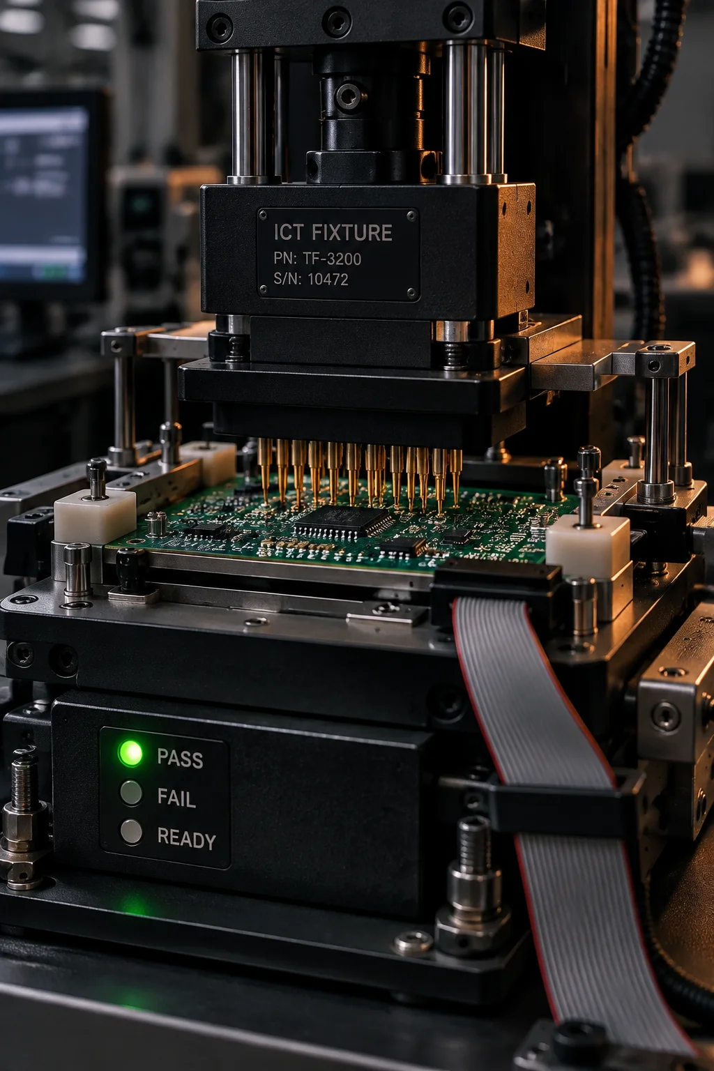
Vertical bed-of-nails test fixture with a probe plate, guide pins and a fixture cable loom staged on a bench

Functional test log

A functional test log with the limits written in

Seven measured parameters from a motor-control programme, each against its own lower and upper limit at a stated condition. The log is attached to the serial number, so a field question can be answered from the record rather than from a re-test.

fct-log / MTR-2251 / serial 0004187
programme   MTR-2251 - 4-layer motor controller, 24 V rail, 6 A load
condition   25 C ambient, 24.0 V input, firmware 3.1.4, 6 A resistive load
parameter              limits              measured      result
supply current, idle    18-26 mA            21.4 mA       PASS
supply current, 6 A     5.90-6.30 A         6.08 A        PASS
logic rail             3.234-3.366 V       3.301 V       PASS
hall offset            -12 to +12 mV        +4 mV         PASS
commutation freq       19.6-20.4 kHz        19.98 kHz     PASS
thermal rise, 10 min   max 28 C           31 C          FAIL
retest      heatsink seating corrected, 10 min soak repeated
thermal rise, 10 min   max 28 C            24 C          PASS
disposition rework pass 1 recorded against serial 0004187, limit unchanged
coverage    97.4% of nets electrically verified, residual list attached
RELEASED    all limits met at the stated condition, 1 rework pass logged

Development deliverables

Three deliverables that ship with the programme

Test development is quoted as a fixed scope with three artefacts, so nothing about coverage or cost is left to a meeting after the first lot has been built.

TST-01 / Fixture

Fixture design and test-access review

Probe plate layout, probe selection for the pad geometry, guide-pin and tooling-hole placement, and a mechanical cradle where the board has no probe access at all. The review runs at layout, so the changes that make a fixture cheap are made before the artwork is released rather than after.

Fixture cost
$2,000-50,000 in-circuit, $1,000-10,000 functional
Lead time
4-8 weeks in-circuit, 1-2 weeks functional

TST-02 / Program

Test program and limit definition

The program that drives the board, the limit table that decides pass or fail, and the boundary-scan chain where the design carries one. Every limit names its condition and its instrument, and the program writes a serialised result file rather than a red or green lamp, so a dispute can be settled from data.

Program development
$2,000-10,000 for in-circuit, hours for flying probe
Boundary-scan setup
1-2 weeks for chain validation

TST-03 / Report

Coverage report and residual escape list

A per-net and per-defect accounting of what is verified, what is verified indirectly, and what is not verified at all. The residual list is the commercial part of the document: it names the defects the programme is choosing to carry, so the decision is made deliberately instead of being discovered from a field return.

Typical coverage
95-99% of nets on a design with full test access
Delivered
With the first-article report, revised per engineering change

Method economics

Flying probe against in-circuit against functional test

The three electrical methods differ less in what they measure than in how the cost is shaped. The table below is the comparison we put in front of a buyer when a volume band is still moving.

Electrical test methods compared at a 900-node board, industry-typical bands
Comparison Flying probe In-circuit test Functional test
Fixture or setup None; probe program only Bed-of-nails fixture with a probe plate Interface harness or cradle with a mating connector set
Setup cost $0 NRE beyond programming hours $2,000-50,000 depending on node count and side access $1,000-10,000 for the fixture and program
Lead time to first run Hours 4-8 weeks 1-2 weeks
Cost per board $3-10 $0.50-2.00 after the fixture is amortised $1-10 board level, $5-25 system level
Cycle time 1-10 minutes 5-30 seconds 30 seconds to 5 minutes
Volume band where it wins 1-1,000 boards, and any high-mix low-volume programme Above roughly 3,000 boards, and 10,000 plus without argument Every band, because nothing else confirms behaviour
What it leaves open Joint integrity under vibration, and RF behaviour above the probe bandwidth Marginal joints that pass under probe pressure, and any parameter that drifts with temperature Marginal timing and wear-out, which only cycling or field data reveal

The volume figures above are planning bands, not a price list. A programme that mixes high node count with low volume is usually priced on flying probe even at 5,000 boards, because the fixture cannot be amortised across enough revisions.

Macro record

The test cell the strategy is executed in

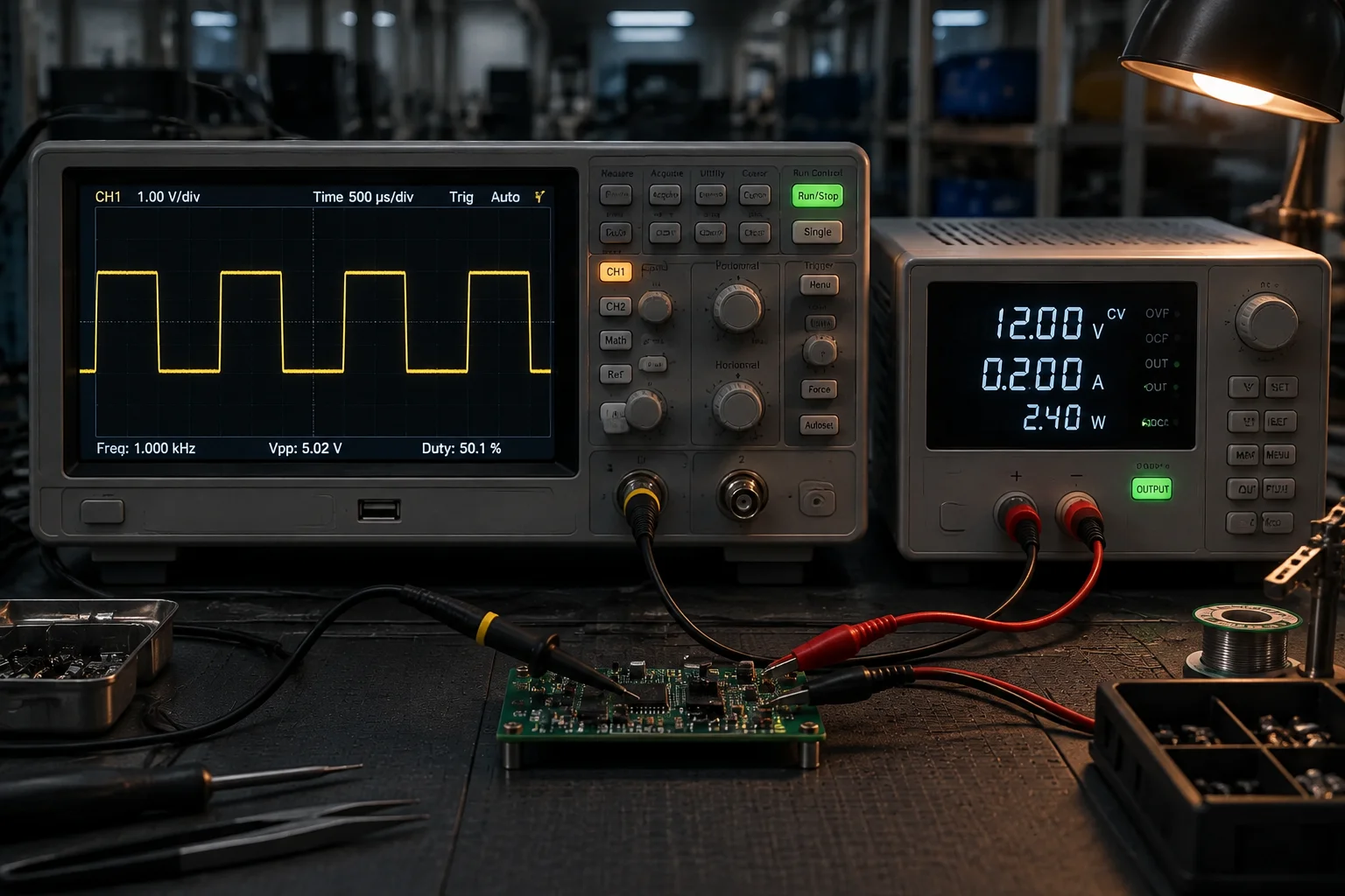
A loaded fixture, an instrument rack and a serialised result file. The physical arrangement matters because probe pressure, cable routing and grounding all change the measurement the limit table was written against.

Test cell with a board seated in a fixture, probe plate closed and an instrument rack logging serialised results beside it
Test cell / fixture closed on a loaded board Every result written against the board serial, not the batch

Buyer questions

Fixture payback, test access and how coverage is chosen

Get Quote Call Us
marker. Behaviour comes from inquiry-handler.js via data attributes — no inline JS, no onclick, no inline style (CSP: script-src 'self'; style-src 'self'). ============================================================================ --> marker. Behaviour comes from inquiry-handler.js via data attributes — no inline JS, no onclick, no inline style (CSP: script-src 'self'; style-src 'self'). ============================================================================ --> marker. Behaviour comes from inquiry-handler.js via data attributes — no inline JS, no onclick, no inline style (CSP: script-src 'self'; style-src 'self'). ============================================================================ -->