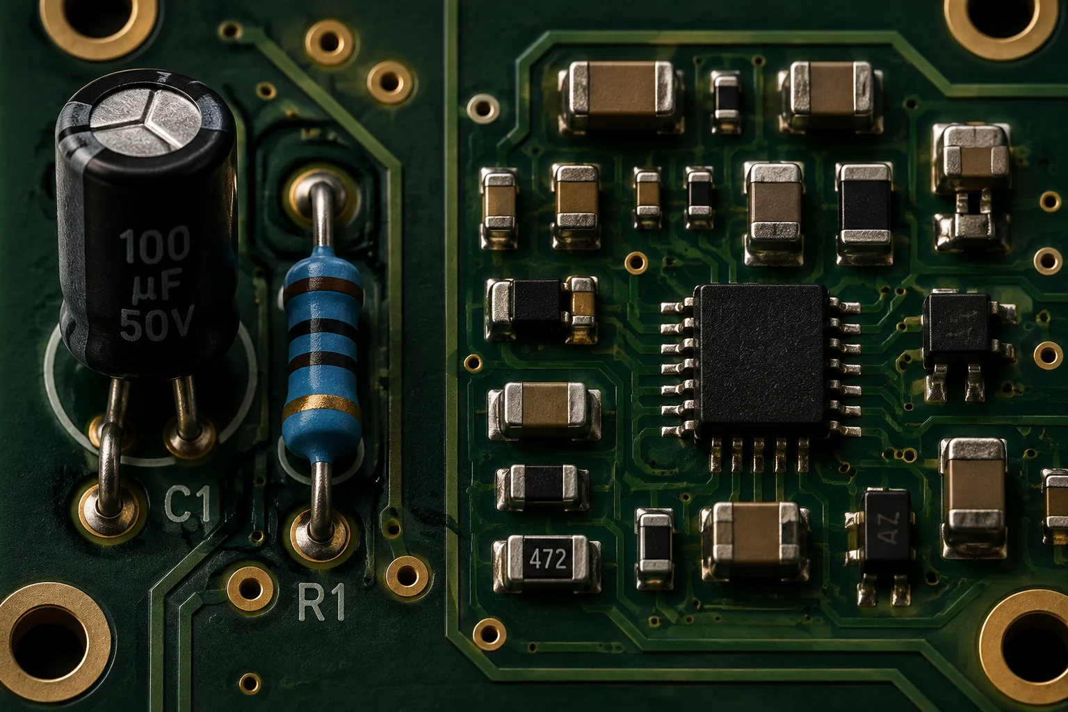
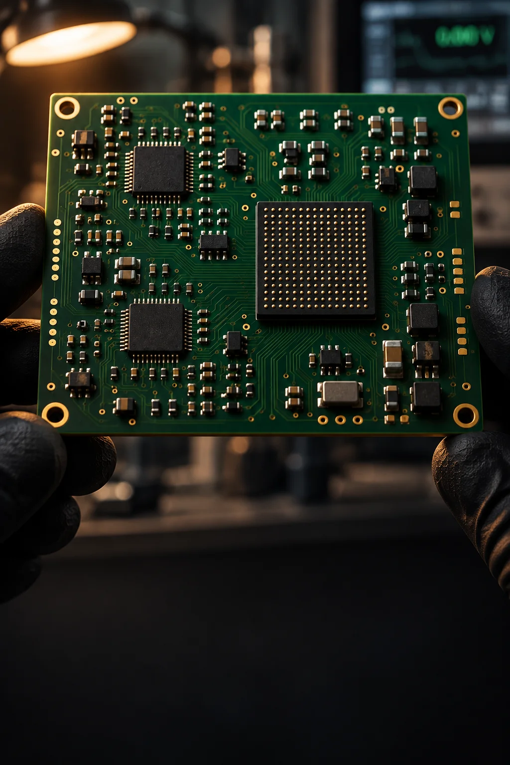
Mixed-technology board carrying dense surface mount sections beside heavy through-hole connectors and power devices

Mixed technology / SMT and THT on one floor

Mixed-Technology Assembly Under One Roof

Most industrial products are not purely surface mount or purely through-hole. They carry a reflowed logic section, a connector row that needs mechanical strength and a mechanical stack on top. Keeping all three steps in one building removes the hand-off where boards get lost, re-inspected and re-quoted.

Add the box build

3 passes maximum reflow exposures
1 panel minimum production release
1 serial across every process step

Scope

What a mixed-technology build covers

Twelve parameters that describe the process as it is actually run, including the ones that limit how many times a board can go through an oven.

Mixed-technology scope - 12 parameters - one traveler per assembly
Parameter What it covers Limit or note
Technology mix Reflowed SMT, through-hole, press-fit and electro-mechanical steps on one assembly One build order, one serial
Reflow exposures Two SMT passes plus one pin-in-paste pass before the thermal budget is reviewed Maximum 3 passes
Second-side attachment UV or thermal-cure adhesive dots under heavy bottom-side parts $0.01-0.03 per component
Pin-in-paste Through-hole connectors printed and reflowed with the SMT side 1:1 aperture, 0.1-0.2 mm overprint
Selective soldering after SMT Connector rows finished with a 3-6 mm nozzle under nitrogen Oxygen below 1,000 ppm
Mixed alloy control SAC305 and SnPb kept apart through pots, irons and profile libraries Separate consumables and pots
Press-fit Compliant-pin connectors inserted after reflow with no solder joint 60-120 N per pin
Assembly thickness Rigid boards from thin wearables up to thick power assemblies 0.4-4.0 mm; above 4.0 mm selective only
Panel handling Rail and tab design plus support pins under heavy through-hole parts 5 mm rail, 2.0 mm tabs
Thermal mass control Soak profile that brings a heavy connector and a 0402 part to liquidus together Cold-spot delta under 12 C
Coating sequence Conformal coating applied after every solder and press-fit step Solderable surfaces masked
Mechanical steps Torque-controlled fastening, staking, potting and labelling on the same traveler Torque logged per fastener

Build sequence

Three stages that define the routing

Every mixed-technology assembly is planned as this sequence. Moving a step changes the panel design, not just the schedule.

SEQ-01 / Print, mount, reflow

The reflowed logic side

Paste is printed through a 100-150 um foil chosen for the finest pitch on the board, passives are shot at 40,000-80,000 CPH, and fine-pitch ICs are placed in vision mode. One 10-zone profile covers the side at a 217 C liquidus.

SEQ-02 / Second side

Flipping without losing parts

Adhesive dots hold anything above roughly 3 g before the board is flipped, then the second side is printed, placed and reflowed at a lower peak so the first pass is not disturbed. Cold-spot delta across the panel stays under 12 C.

SEQ-03 / THT finish

Connectors and mechanical strength

Connector rows that need mechanical strength are soldered by selective nozzle or wave, press-fit parts are inserted at 60-120 N per pin, and the assembly is cleaned, coated, labelled and functionally tested before it is packed.

Single source

One traveler instead of two suppliers

Splitting SMT and through-hole work across two shops looks cheaper on a quotation and rarely is once the hand-offs are counted.

One serial, three processes

The panel ID is applied before the first print and follows the assembly through reflow, selective soldering, press-fit and system test. A single record shows laminate lot, component lot and date code, profile, and every inspection result.

Changeover you can plan around

Mixed-model changeover between a reflow-only board and a full mixed-technology build takes about 4 hours, including stencil swap, nozzle change and profile validation. That is what makes a 1-panel production release economic.

Thermal budget agreed up front

Reflow exposures are capped at 3 per assembly. Where a design needs a fourth pass, the DFM note proposes pin-in-paste, an adhesive-dot alternative or a selective route instead of quietly exceeding the budget.

Rework stays in the building

If a connector fails functional test after the SMT side is complete, the same team desolders it under IPC-7711 and 7721 procedures rather than returning a partly assembled board to another supplier.
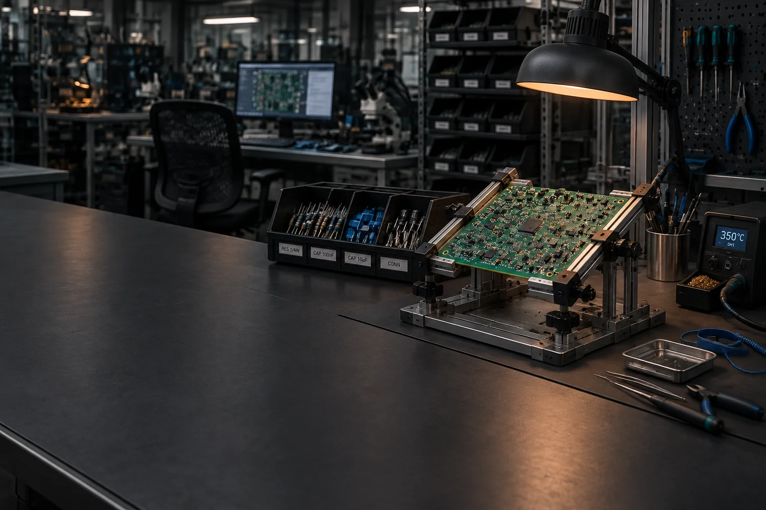
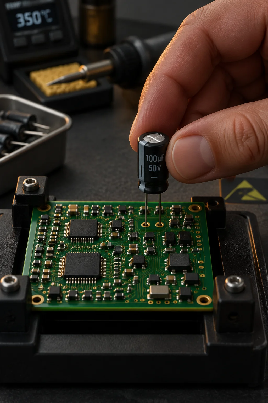
Close view of a mixed-technology board mid-assembly with a connector row framed by dense surface mount sections

Comparison

Split supply chain against one supplier

The same board built two ways, scored on the eight factors that show up in a programme review after the first shipment.

Split supply chain compared with single-source mixed-technology assembly
Programme factor Split supply chain Single source at GENESIS CIRCUITS
Hand-offs Two packing, shipping and receiving cycles per lot One traveler, no outbound leg
Lead time Adds 3-7 working days per hand-off Quoted as one schedule
Traceability Two record sets that must be reconciled by part number One serial covering every process step
Thermal history Second supplier rarely knows the first profile Reflow exposures capped at 3 and logged
Rework ownership Contested when a joint fails after the second build One team owns the rework record
Inventory Two WIP pools and two minimum stock positions One WIP pool, released from 1 panel
Change control Revision must be frozen twice One frozen revision across all steps
Failure cost Scrapped value includes freight both ways Scrap is detected before the mechanical stack is fitted

Macro record

A finished mixed-technology assembly

Finished mixed-technology assembly showing a reflowed logic section, a through-hole connector row and a press-fit power connector
Reflowed logic side, selective-soldered connector row, press-fit power connector Built, cleaned, coated and tested under one serial

Questions

Mixed-technology questions from programme reviews

Get Quote Call Us
marker. Behaviour comes from inquiry-handler.js via data attributes — no inline JS, no onclick, no inline style (CSP: script-src 'self'; style-src 'self'). ============================================================================ --> marker. Behaviour comes from inquiry-handler.js via data attributes — no inline JS, no onclick, no inline style (CSP: script-src 'self'; style-src 'self'). ============================================================================ --> marker. Behaviour comes from inquiry-handler.js via data attributes — no inline JS, no onclick, no inline style (CSP: script-src 'self'; style-src 'self'). ============================================================================ -->