Sector / Energy, power conversion and storage
PCBA for Energy, Power Conversion and Storage
Energy hardware fails for two reasons that a low-voltage board never meets: the isolation has to hold at a bus voltage in the hundreds or thousands of volts for twenty years, and the power joints have to survive thermal cycles that crack a marginal fillet long before the warranty ends. Both are decided by process control, not by inspection at the end.
Buyer pain points
Where energy and power programmes actually lose money
Every row is a cost that appears after the hardware is installed, which is why none of them can be tested away at the end of the line.
| Pain point | The number | Consequence if it is left unmanaged |
|---|---|---|
| Isolation at high DC bus voltage | Battery storage rack monitors are designed around a 1500 V stack, and utility string inverters run DC inputs at 1000 V or more. | An isolation gap that satisfies the drawing but not IEC 60664-1 fails the certification test after tooling is cut, and widening the barrier later fragments the ground plane. |
| High-current joints and thermal mass | Power stages use 2-6 oz copper, thermal via arrays and module solder layers that carry the full load current. | A joint with 20% voiding passes a visual check and becomes a hot spot that opens the circuit years later, usually at the worst point in the load profile. |
| Certification evidence from the board upward | UL 1741 for inverters, IEC 62109-1 and IEC 62109-2 for converters, and UL 9540 with UL 9540A testing for storage systems. | A missing board-level creepage measurement, material declaration or hipot record becomes a test-house finding, and the retest lands inside a production ramp. |
| Field-failure liability in remote installations | Installed electronics are expected to serve 10-20 years, and a truck roll to a remote site can cost more than the board it replaces. | A 1.8% joint failure rate across a 5,000-unit fleet is 90 site visits with access, permit and lost-generation cost attached to each one. |
How the build is run
Thermal mass, isolation and high-voltage test on the same panel
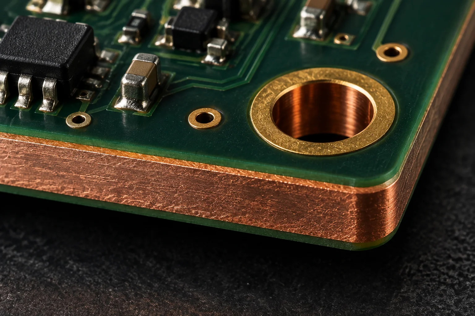
Heavy copper and high-current joints
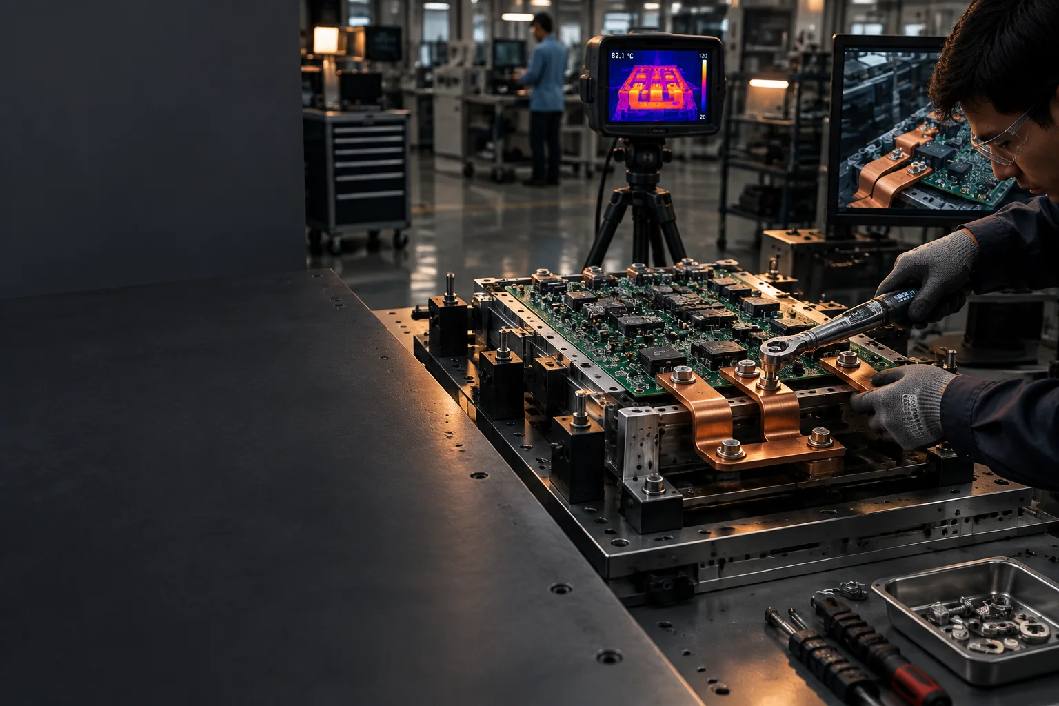
A 4 oz power plane pulls heat out of a joint far faster than the fine-pitch control section beside it, so the two areas get different paste volumes, different preheat and, where the mass demands it, different soldering processes. High-mass connectors and press-fit terminals go through the selective cell with a dedicated nozzle, press-fit force is measured rather than felt, and bolted busbar joints are torqued to a logged value. Void content on the module solder layer is measured by X-Ray on every unit, because voiding is the mechanism behind most power-stage thermal failures.
Insulation coordination at the drawing stage
Creepage and clearance are reviewed against IEC 60664-1 at the working voltage the system will actually see, with the pollution degree and the overvoltage category fixed before the stackup is released. The laminate's comparative tracking index is named on the traveller, because a standard FR-4 at 175-250 V and a high-CTI material at 600 V look identical on the shop floor. Isolation slots, routed barriers and coating coverage across the barrier are all protected through assembly rather than added afterwards.
High-voltage test with real safety fixtures
Hipot is run at the programme voltage with interlocked fixtures, a defined ramp and a leakage limit recorded per serial, never as a pass stamp on a batch. Thermal cycling from -40 to +125 C and power cycling at a controlled junction temperature rise are the two tests that separate a joint that will last twenty years from one that will not, and the resistance drift after cycling is reported alongside the pass or fail result.
Requirements to capability
What a power programme asks for and what this plant provides
The standards in the second column are the ones a certifier, an insurer or a utility interconnection reviewer will name, so they are mapped to the record that supports them rather than to a general capability claim.
| Requirement | Governing standard | What we do | Evidence |
|---|---|---|---|
| Grid-tie inverter safety | UL 1741, IEC 62109-1 | DFM review of the isolation barrier and the creepage path at the DC input voltage, with the assembly record packaged so it can be lifted into the system test file. | Barrier measurement report and design review notes |
| Storage system awareness | UL 9540, UL 9540A, UL 1973 | BMS and rack-monitor assemblies built with a defined cell-interface isolation drawing and documented separation between the sensing and power domains. | Process and material records aligned to the system test file |
| Power conversion equipment | IEC 62477-1 | Clearance and creepage values applied at the working voltage, with the coating system selected for the pollution degree the enclosure actually provides. | Insulation coordination worksheet per build |
| Insulation coordination | IEC 60664-1 | Creepage and clearance checked at 1000-1500 V DC, with the comparative tracking index and material group locked in the traveller at award. | Laminate certificate naming the tracking index |
| Heavy copper processing | 2-6 oz outer layers | Reflow soak and preheat tuned to the copper mass, with thermal relief, via arrays and copper balance reviewed before the stencil is cut. | Profile record and plated-through-hole cross-sections |
| Thermal path under power devices | IPC-7095 void criteria | Thermal via arrays, copper coin inserts and aluminium metal-core options, with void percentage measured on the module solder layer rather than judged by eye. | X-Ray images with void percentages per serial |
| High-current interconnects | IPC/WHMA-A-620 for the harness side | Press-fit, busbar and bolted lug assembly with press-fit force logged and every fastener torqued to a recorded value within a stated range. | Press-fit and torque records per unit |
| Solder-joint integrity | IPC-A-610 Class 3 | Class 3 workmanship on the power section with no sampling, 100% X-Ray on module and BGA joints and a documented fillet inspection at the barrel. | Inspection record signed by a certified inspector |
| Dielectric withstand | IEC 62109-1, programme test specification | 100% hipot at the programme test voltage with an interlocked fixture, a defined ramp and a leakage-current limit recorded against the serial number. | Serialized hipot record with measured leakage |
| Thermal and power cycling | IPC-9701, JESD22-A104 | Thermal cycling from -40 to +125 C and power cycling at a controlled temperature rise, with joint resistance monitored before and after. | Cycle report including resistance drift |
| Outdoor enclosure protection | IPC-CC-830 | Conformal coating at 25-75 µm cured thickness with connectors masked, keep-outs respected and cure verified on a witness coupon per batch. | Coupon thickness and cure record |
| Warranty traceability | Programme requirement | Serialized records back to the panel, reflow profile, paste lot and X-Ray images, sized for a product that will be serviced in the field for a decade or more. | Serial traceability index on release |
High-voltage and thermal test
Hipot, void and cycling results as they are reported
This is the summary returned with a power programme. The values are what the lot was measured at, next to the limit it was measured against.
programme    NRG-5121 - 6-layer, 4 oz outer copper, Tg 180 C
topology     three-phase string inverter power stage, 1000 V DC input
hipot        PASS  2.5 kV AC, 60 s, leakage 0.31 mA against a 5 mA limit
creepage     PASS  8.6 mm measured against the 8.0 mm minimum, Pollution Degree 2
clearance    PASS  5.4 mm measured against the 5.0 mm minimum
void         PASS  4.2% maximum on the module solder layer, limit 10%
thermal      PASS  -40 C to +125 C, 200 cycles, no via-barrel crack
power cycle  PASS  5,000 cycles at 80 C rise, thermal resistance drift under 4%
coating      52 um acrylic, witness coupon per batch
records      serialized; hipot and X-Ray images attached to the serial
Programme record
An inverter power stage taken from 1.8% field returns to 0.2%
The four elements a buyer asks for: what the programme was, what the requirement was, what changed, and what the numbers did afterwards.
Record
Programme
- Sector
- Solar power conversion
- Programme
- NRG-5121
- Volume
- 1,800 units per year
- Class
- IPC-A-610 Class 3 on the power section
Requirement
What the customer brought
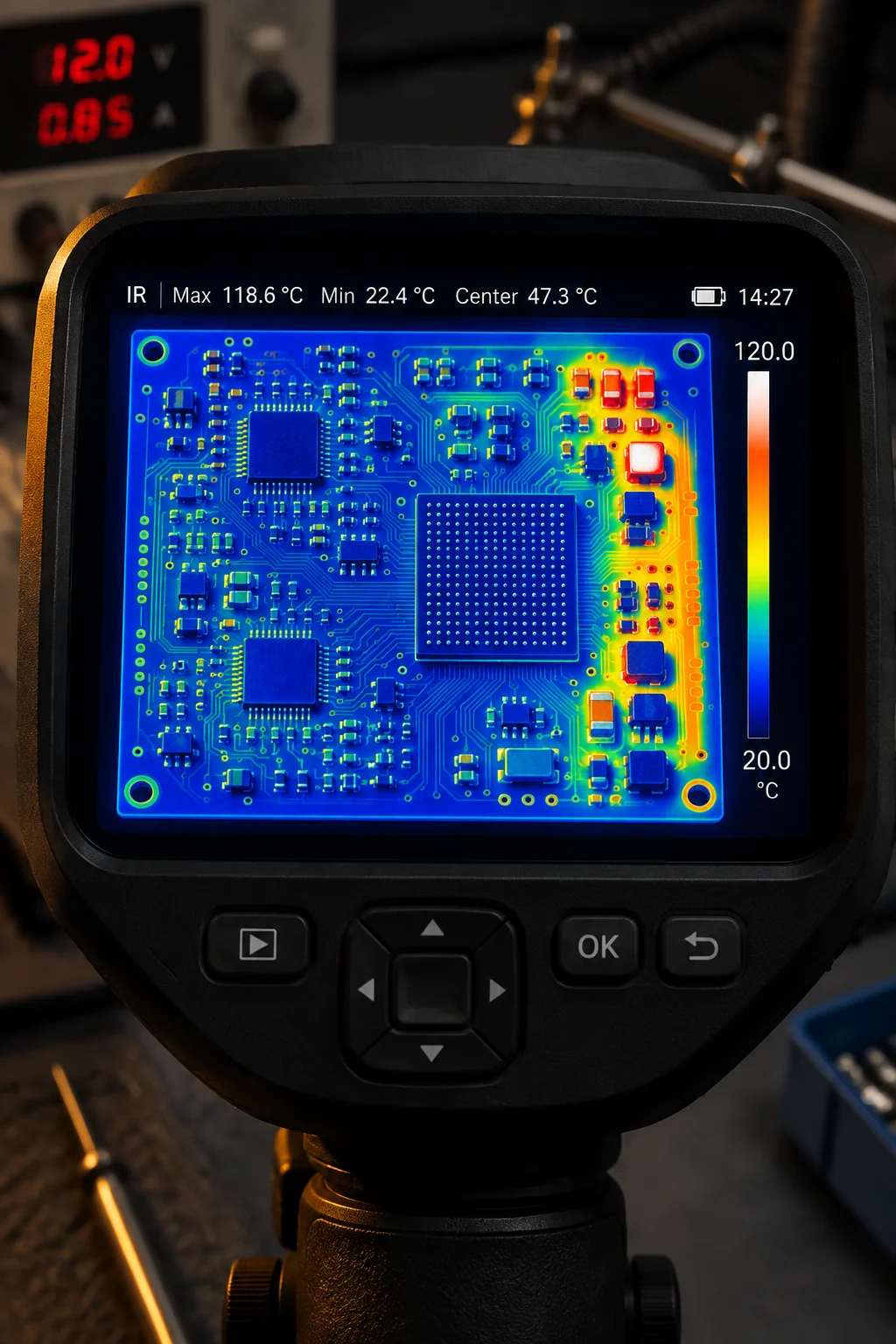
A three-phase commercial string inverter with a 1000 V DC input and a boost stage built on 4 oz copper. Twelve months of field data showed a 1.8% return rate concentrated on the boost-stage MOSFET joints, with returns clustered in installations that saw the widest daily temperature swing. The board passed hipot and functional test on the line, so the defect was thermal fatigue rather than an assembly escape.
Action
What we changed
A 96-via thermal array was added under each MOSFET footprint and the copper balance around them was rebuilt to even out the heat path. The reflow profile gained a longer soak and a slower ramp into the peak to cut voiding under the thermal pad, the module joints moved to 100% X-Ray with the void percentage recorded per serial, and the busbar fasteners moved to a logged torque value with press-fit force measured on every unit.
Result
What the numbers did
Void content on the module solder layer fell from a 14% maximum to 4.2%, and the lot passed 200 thermal cycles from -40 to +125 C with no via-barrel crack and a thermal resistance drift under 4% after 5,000 power cycles at an 80 C rise. Hipot first-pass moved to 99.6% at the 2.5 kV AC test, and the field return rate on that programme settled at 0.2% over the following twelve months.
Buyer questions
Certification evidence, mixed processes and remote failures
The system certificate is yours to hold, but the test house needs board-level evidence underneath it, and that is what we produce: creepage and clearance measurements against IEC 60664-1 at the working voltage, the laminate certificate naming the comparative tracking index and material group, hipot records with the leakage current at the test voltage, X-Ray void data for the power-module joints, and a material declaration covering RoHS 3 and REACH. UL 1741 for inverters, IEC 62109-1 and IEC 62109-2 for power converters and UL 9540 awareness for storage systems all draw on the same record set, which is indexed by serial number.
Yes, and it is the normal shape of a storage rack monitor or a three-phase inverter board. The power stage runs 2 to 6 oz copper through a soaked reflow profile or the selective-soldering cell, while the isolation and control sections need finer features and a tighter assembly window on the same panel. The two compete for thermal mass, so the profile, the stencil apertures and the paste volume are set separately per zone and the press-fit and busbar connections are made after reflow, with force and torque logged rather than estimated.
The serial number resolves to the panel, the reflow profile, the paste lot, the X-Ray images and the hipot record for that specific board, so a failure can be classified before anyone travels to site. Where the failure is a joint or a process cause, we list the affected serial range from the same records, which turns a fleet-wide recall into a targeted replacement. For a 5,000-unit fleet, a 1.8% joint failure rate is 90 site visits, so the record that bounds the suspect population is worth more than any cosmetic rework.