Manufacturing Notes · New product introduction
The NPI Checklist That Prevents a Bad First Build
A first build fails for boring reasons: a footprint that does not match the part, a BOM line that went end-of-life last quarter, a test limit that nobody wrote down. This note is the gate list we run before a pilot panel is released, together with the lead times each gate actually costs.
Published 22 January 2026 · updated 10 February 2026 · 9 min read · Daniel Wong, Manufacturing Engineer
The five decision points
Five things that decide a first build
Each of the five notes below is a point where a programme either freezes a decision or spends money twice. They run in a single column in the order the work arrives: data, then material, then process, then test, then the build itself.
Note 01
Data package: what has to be frozen
Gerber RS-274X with an NC drill file, ODB++ or IPC-2581, a BOM with manufacturer part numbers, a pick-and-place export and a drawing that states the stack-up. Freeze all five before the stencil is ordered. A single revision mismatch between the Gerber and the paste layer produces a panel that places correctly and reflows into bridges, and the loss is a full stencil plus a shift on one of the six SMT lines, against ANSI/ESD S20.20 handling rules and the ISO 9001:2015 document control that governs the release.
Note 02
Footprint and land pattern verification
Verify every package against the library before placement: 01005 at 0.4 × 0.2 mm, 0201, 0.35 mm leadless pitch and 0.4 mm leaded pitch all have different tolerance budgets. Our placement accuracy is plus or minus 15 to 25 µm on ultra-fine-pitch parts, which is not enough headroom to absorb a courtyard that was drawn 0.1 mm too small. This check costs an hour and removes a class of rework that costs days.
Note 03
BOM lifecycle and second sources
Every line gets a lifecycle status at quotation. A part marked end-of-life or last-time-buy is a schedule risk, not a pricing problem, and the correct moment to find out is before the pilot. Where a second source exists, name it on the approved vendor list in advance; where it does not, decide who owns the bridge buy. Roughly one BOM in four that reaches us carries at least one line needing attention before release.
Note 04
Process window and thermal profile
Set the stencil thickness (100 µm, 120 µm or 150 µm) against the finest aperture, then build the profile on a 10-zone forced-convection oven. SAC305 runs a 217 degrees C liquidus, and a mixed-technology board with heavy ground planes needs soak and ramp-to-spike profiles tested separately. Acceptance limits belong in the traveller: BGA void under 25% for Class 2 and under 10% for Class 3, ionic contamination at or below 1.56 µg NaCl/cm² for Class 2 and 0.78 µg NaCl/cm² for Class 3.
Note 05
Test strategy and coverage proof
Decide what has to be proven electrically before the fixture is quoted. An ICT fixture runs 2,000 to 50,000 USD with a 4 to 8 week development lead time; functional test fixtures run 1,000 to 10,000 USD in 1 to 2 weeks; flying probe needs no fixture at about 3 to 10 USD per board. Write the limits down at the NPI stage, because a limit invented after the first failures is a limit that will move again.
Gate list
The twelve NPI gates, in sequence
Each gate names the evidence that closes it. A gate is not closed by a conversation; it is closed by a signed record in the traveller, which is what makes the pilot auditable later.
| Gate | Stage | Evidence that closes it |
|---|---|---|
| G-01 | Data intake | Gerber, drill, BOM and pick-and-place received and revision-locked |
| G-02 | DFM review | Marked-up deviation list returned and answered by the customer |
| G-03 | Footprint audit | Every package checked against pad geometry and courtyard clearance |
| G-04 | BOM lifecycle | End-of-life and last-time-buy lines flagged with an owner and a decision |
| G-05 | Panelisation | Panel drawing approved, breakaway and fiducial positions fixed |
| G-06 | Stencil and paste | Stencil thickness chosen against the finest aperture ratio below 0.66 |
| G-07 | Material release | Every BOM line received or committed with a dated purchase order |
| G-08 | Incoming inspection | IQC pass on part marking, reel count, MSL handling and XRF where needed |
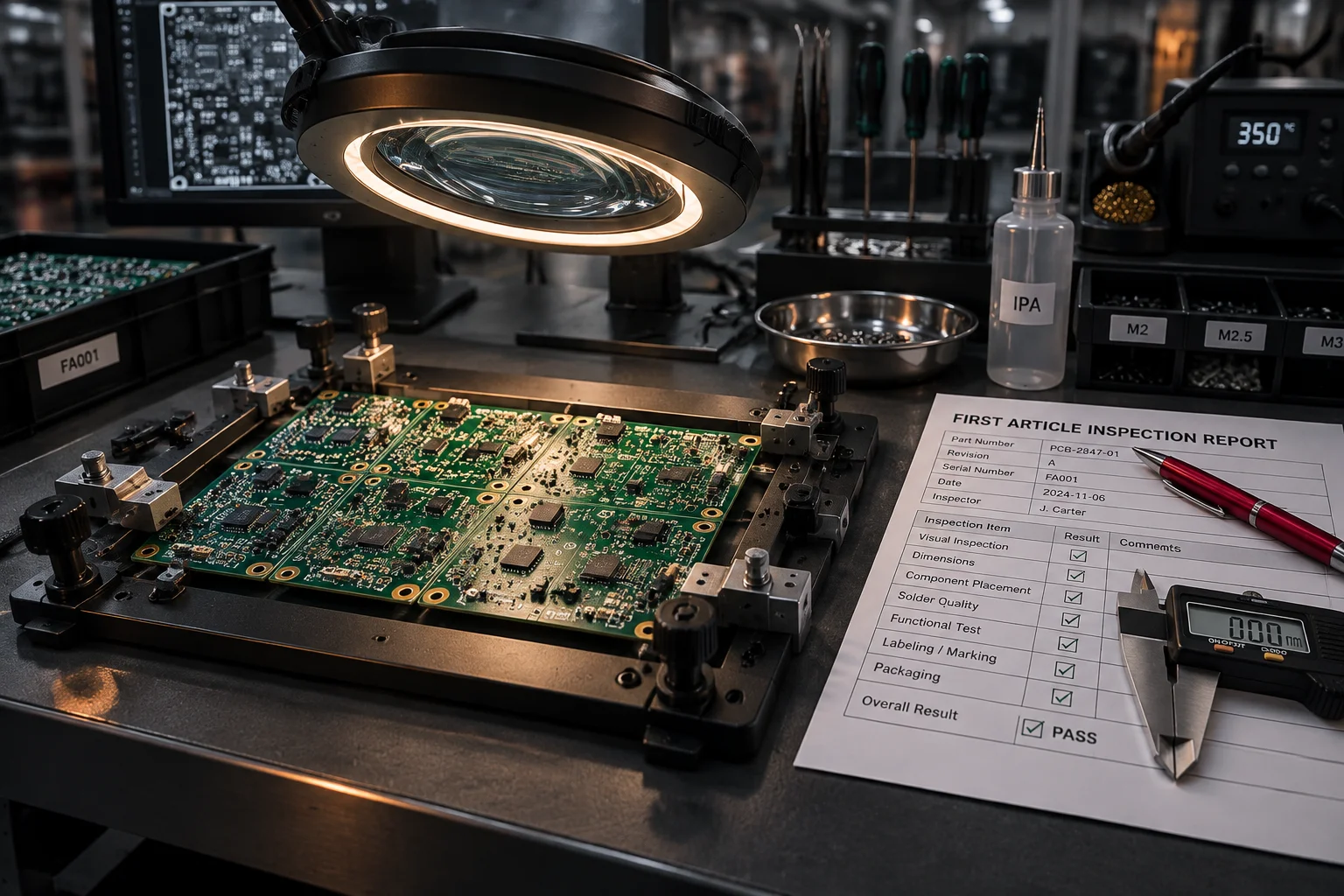
| G-09 | Profile and first article | Reflow profile recorded and the first unit inspected to IPC-A-610 |
| G-10 | Test development | Fixture or flying-probe program released with the limit set signed off |
| G-11 | Pilot release | Pilot panel built, AOI and X-ray complete on every BGA and QFN |
| G-12 | Production handover | First-pass-yield data, first-article report and the traveller archive filed |
What each gate costs in calendar time
| Step | Working days | Depends on |
|---|---|---|
| Data intake and revision lock | 1 | Complete data package from the customer |
| DFM review and mark-up | 1–2 | Answers on the deviation list |
| Component sourcing and commitment | 3–15 | Longest component lead time in the BOM |
| Stencil and fixture order | 2–5 | Stencil ordered with the panel drawing |
| Pilot SMT build | 1–2 | Material released to the line |
| Through-hole and selective solder | 1–2 | Pilot SMT schedule |
| AOI, X-ray and first article | 1 | Build complete |
| Functional test and release | 1–3 | Program released and limits signed off |
A simple 2-layer prototype is 3 to 5 working days end to end; a complex build is 5 to 10 working days. Volume production is 3 to 6 weeks after material release, at typical industry rates. Fixture development, at 4 to 8 weeks for ICT, usually runs in parallel with the pilot rather than before it.
Where the pilot build ends
Reading the first article, then closing the loop
The first article is the earliest point at which the process can be judged honestly, and it is the cheapest point at which to change anything. Assembly first-pass yield sits at 99.4% with 0.42% DPMO on SMT placements, so the article is read for the shape of the failures rather than for the count.
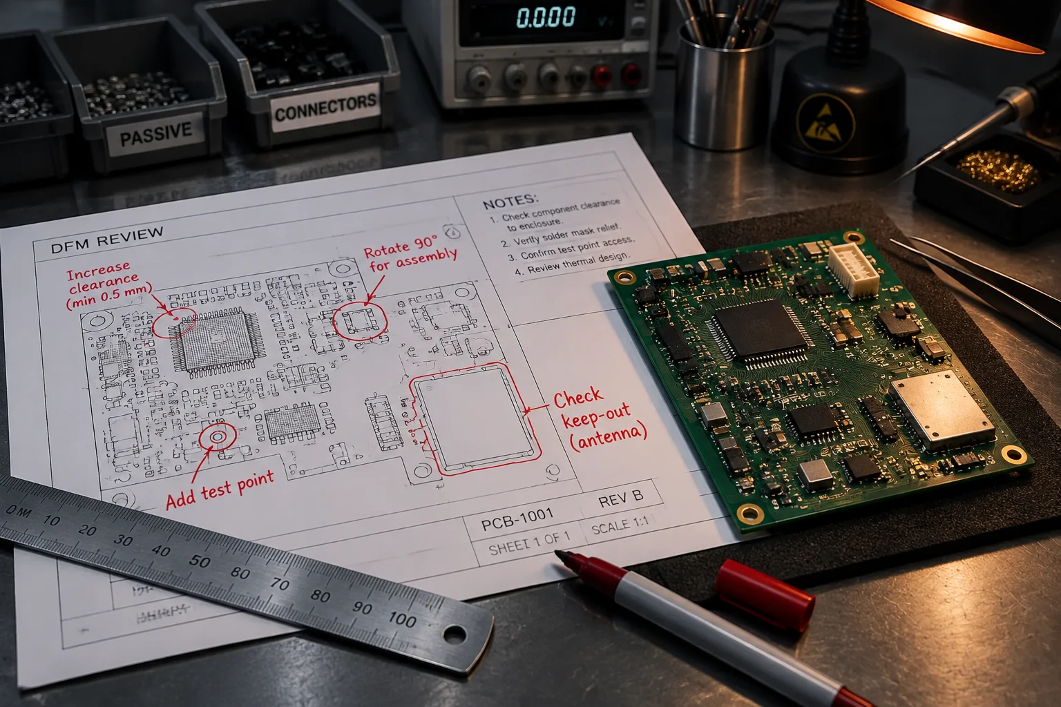
IPC-A-610H process targets: 2 to 5% rejection for Class 2 and 8 to 15% for Class 3. A first article outside those bands is a process signal, not an operator problem.
Reader questions
Asked after this note went out
As soon as the schematic is frozen and before the bare board is ordered. Footprint, courtyard and panelisation problems are free to fix at that point and expensive once boards exist. Once Gerbers are released the only cheap lever left is the stencil aperture, and that recovers paste volume defects rather than geometry mistakes.
For any board with a BGA, a fine-pitch part below 0.4 mm pitch, or a mixed-technology assembly, yes. A pilot panel costs one panel of material and a day of line time, and it converts process questions into measured answers before the first shipment. For a 2-layer board with 0805 passives and a handful of through-hole parts, the first production run is the pilot.
Component commitment, and it is rarely the fault of the design. Lead time in our data runs from 3 to 15 working days on sourced material and the binding date is the longest line in the BOM, not the line schedule. Freezing the BOM two weeks earlier moves the build date more reliably than any queue shortcut on the floor.